Your cart is empty
 Short Rigid Couplings
 Controlflex Couplings
 Jaw Couplings
 Oldham Couplings
 Bearing Locknuts – TCN
 Double Wide Shaft Collars
 Heavy Duty Shaft Collars
 International Series Shaft Collars
 Keyed Shaft Collars
 Mountable Shaft Collars
 Quick Clamping Shaft Collars
 Set Screw Shaft Collars
 Thin Line Shaft Collars
 Threaded Shaft Collars – Pacific International Bearing Products
 Two-Piece Shaft Collars
 Friction Bearing Universal Joints
 Needle Bearing Universal Joints
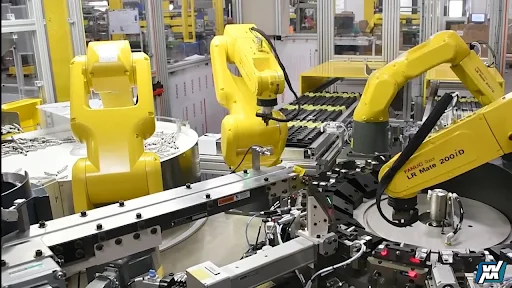
Bearings
Bearings Used in Assembly Robots
03 April, 2026
18 min read
Bearings are the mechanical “truth layer” in an assembly robot: they turn servo torque into repeatable motion while carrying combined radial (Fr), axial (Fa), and moment (M) loads in compact joints and linear axes. Pacific International Bearing Sales (PIB) typically selects bearings by robot node and environment first because stiffness, sealing, and lubrication choices decide whether you get smooth cycles or creeping drift and downtime.
Key Takeaways
- Robot joints rarely see “simple” loads; most accuracy problems trace back to combined Fr/Fa/M and insufficient stiffness or preload.
- The most common bearing families in assembly robots are crossed roller, angular contact, thin-section, spherical plain, miniature ball bearings, and linear guides—each solves a different constraint.
- n×dm is the fastest way to sanity-check speed / lubrication stress; it’s not a detail—it’s a risk flag.
- Most “mystery” failures are predictable: contamination, false brinelling/fretting from micro-motion, smearing from poor clamping/preload, or lubricant breakdown.
- Your best ROI move is aligning bearing choice + sealing + lubrication strategy with service reality (sealed-for-life vs planned relubrication vs built-in lubrication).
Bearings in assembly robots do three jobs at once: they carry load, they define geometry, and they manage friction/heat. You can hit torque and speed targets with a big motor, but you only hit repeatability when the bearings keep the axis stiff and stable over time, especially as temperature and lubricant conditions change.
The “robot joint reality”: combined loads, not textbook loads.
A robot joint almost never sees purely radial load. In assembly cells, loads are typically a blend of:
- Fr (radial load): the “side load” from arm weight, belt tension, and reaction forces.
- Fa (axial load): thrust from gear meshes, harmonics/strain-wave stages, or tool forces aligned with the axis.
- M (moment load): the big one created by tool offset, payload at reach, acceleration, and any side contact (press-fit, insertion, screwdriving misalignment).
IKO summarizes why this matters: crossed roller bearings are attractive in robotics because they can handle radial, thrust, and moment loads at the same time—which is exactly what joints see in real motion profiles.
Node-by-node: where the bearings “live” in an assembly robot.
Assembly robots usually break down into a few bearing “ecosystems”:
- Base / A1: big moment loads + stability demands
- Shoulder / elbow: large load variation + frequent acceleration/deceleration
- Wrist axes: compact packaging + low inertia + high stiffness needs
- EOAT (end-of-arm tooling): miniature mechanisms where small runout becomes real defects
- Linear axes (7th axis, gantry, slides): straight-line accuracy under dynamic load
This “node map” is how many motion suppliers frame robotics selection: IKO explicitly calls out crossed roller bearings for articulated arm rotation and linear guides for repeatable motion, including rail sizes spanning small to large robotic devices.
Bearing Families you’ll Actually Specify in Assembly Robotics
Crossed roller bearings (CRB/CRBH/CRBF families, etc.)
If you need high rotational accuracy and stiffness in a compact joint (base, wrist, indexing head), crossed roller bearings tend to be first on the bench. IKO describes the core geometry: rollers are crossed at right angles between inner and outer rings, enabling one bearing to take radial, thrust, and moment loads simultaneously, which is why they’re common in industrial robots.
The IKO crossed roller bearing catalog reinforces the design intent: “taking load of any direction and moment at the same time” and emphasizing rigidity and space saving.
What engineers often miss: crossed roller bearings behave like structural members. Small changes in housing geometry, fastener stiffness, and mounting flatness can show up as axis compliance and micro-tilt often mistaken for gearbox issues.
Angular contact ball bearings (single, duplex, triplex arrangements)
Angular contact bearings are the workhorse when you need controlled axial stiffness and a tunable preload “knob.” NSK explains two fundamentals that matter in robots: (1) the bearing generates an axial component when radial/combined loads are applied, so bearings are commonly used in opposed pairs or multi-bearing arrangements, and (2) preload is often used to increase rigidity.
This is why you’ll see duplex back-to-back (DB) or face-to-face (DF) arrangements in high-stiffness axes, and why assembly errors around locking/clamping can turn into heat, noise, and sliding damage.
Thin-section bearings (constant cross-section, space/weight savings)
In wrists and compact rotary stages, thin-section bearings help you keep inertia down without giving up diameter. SKF (Kaydon)frames the value simply: thin-section bearings maximize available space and help maintain design integrity where “every thousandth of a millimetre matters,” including robotics-type precision applications.
PIB also highlights thin-section bearings as a common inventory class for robotics and automation, reflecting how often designers reach for them when the wrist gets crowded.
Spherical plain bearings (oscillation + misalignment tolerance)
Many robot joints don’t rotate continuously; they oscillate. PIB’s robotics article makes that explicit: joint bearings often oscillate back and forth, and lubrication must survive that motion without drying out—one reason spherical plain bearings with PTFE liners show up as a practical solution.
SKF’s spherical plain bearing catalog backs the broader engineering logic: many applications require bearings that handle oscillating movements and misalignment, which rolling bearings only partly fulfil because they’re generally designed for continuous rotation and accommodate limited misalignment.
Miniature ball bearings (EOAT, sensors, micro-actuators, feeders)
EOAT mechanisms can be mechanically small but quality-critical: a little runout turns into cross-threading, skewed insertion, or inconsistent torque. PIB’s miniature bearing literature notes that miniature/instrument bearings are commonly made in stainless or chrome alloy steels and that life is affected by material and lubrication selection.
If your EOAT is exposed to washdown or fine dust, sealing choice can matter more than load rating.
Linear guides (recirculating rail systems for 7th axis and gantry motion)
For assembly automation, linear axes are often where throughput is won or lost. IKO’s robotics overview states that linear motion rolling guides come in rail sizes from 1 to 85 mm and are used to provide smooth, accurate, rigid, repeatable motion in robotic devices.
On the maintenance side, IKO’s C-Lube concept is designed to extend lubrication intervals and reduce grease work—valuable in cells where access is painful and uptime matters.
Selection Criteria that Actually Change Outcomes
Below is the practical engineer’s checklist. The goal isn’t to sound fancy—it’s to prevent the two classic robot problems: precision drift and surprise maintenance.
Stiffness and moment capacity (not just “load rating”).
Static capacity tells you whether a bearing survives; stiffness tells you whether the robot hits the point under load. For joints carrying tool offset, moment stiffness is often the root requirement—one reason crossed roller bearings are frequently specified for articulated robotic arms where combined loads dominate.
Speed condition via n×dm (and what it implies for lubrication).
PIB defines the speed factor clearly: (n × dm) is rotational speed (rpm) times mean diameter (mm), used to gauge how challenging lubrication and heat dissipation will be at high speed.
SKF uses the same concept in its lubrication selection process and defines mean diameter as dm = 0.5(d + D), using ndm to characterize speed condition; SKF also notes that ndm < 10,000 corresponds to low-speed conditions in their framework.
What this means in robot terms: if n×dm comes out high, you should assume you’ll need “better-than-default” grease (or oil), tighter control of preload/clearance, and possibly a different sealing approach—because heat and lubricant shear become the limiting factor long before fatigue life does.
Sealing choice is a design decision, not a purchasing decision.
PIB’s comparison of open, shielded, and sealed bearings is blunt about the trade: sealed bearings retain lubricant and block contaminants better, often delivering longer life and lower maintenance in dirty conditions, while shields protect less and open bearings demand a clean environment and a lubrication plan.
NSK adds a useful data point from the precision bearing world: sealed designs can extend grease life (NSK cites up to ~50% in one sealed super-precision angular contact context), while also helping prevent contamination and lubricant breakdown.
Lubrication strategy: sealed-for-life, planned relubrication, or built-in lubrication.
PIB’s life guidance is straightforward: lubrication, environment, and maintenance dominate real bearing life; dirt/moisture and degraded lubricant shorten life dramatically, and routine inspection/relubrication is what turns calculated life into achieved life.
If relubrication is feasible, PIB’s maintenance guide notes that relube intervals depend on grease type, dimensions, speed, installation location, and access constraints—which is exactly why robots with cramped wrists often default to sealed solutions.
If relube is hard but uptime is non-negotiable, built-in lubrication concepts like IKO C-Lube are explicitly designed to reduce maintenance requirements over long lifetimes.
Material and corrosion logic (especially in assembly environments).
Robots in electronics assembly, medical device manufacturing, food packaging, or washdown zones are not “normal factory air” applications. IKO explicitly notes stainless options and the ability to modify seals/greases for harsh or sanitation-intensive environments.
Bottom line: specify material and surface protection with the same seriousness you specify Fr/Fa/M.
Preload and mounting discipline (where precision is won or lost).
NSK states plainly that preload increases rigidity in angular contact ball bearings.
SKF’s failure analysis material highlights what happens when bearing pairs aren’t properly clamped: increased axial clearance can lead to ball sliding damage (smearing), more noise, and lubrication problems—classic symptoms that look like “mystery vibration” on a robot axis.
Practical takeaway: treat preload and clamping as controlled process steps (torque, fits, cleanliness), not “installer skill.”
Failure Modes you Should Expect (and How They Show Up in a Robot Cell)
Most bearing failures in assembly robots are not dramatic. They’re subtle: rising torque, rising temperature, noise, vibration, and slowly worsening positional repeatability. The common root causes map well to standard bearing failure taxonomy:
Contamination and particle denting
When debris enters the raceway, denting and surface damage accelerate wear and noise. PIB emphasizes that contaminants like dirt, dust, and moisture can infiltrate and cause abrasion/corrosion, shortening life; sealing/coatings and maintenance are the countermeasures.
False brinelling, fretting corrosion, and vibration damage
Robots spend time stopped (power on, axis held), then move in small oscillations—perfect conditions for micro-motion wear. SKF lists false brinelling and fretting corrosion among common surface-initiated damage modes tied to operating/mounting conditions and vibration.
This is where spherical plain bearings and proper lubricant selection for oscillation can pay back quickly, especially in “back-and-forth joint” regimes.
Smearing / sliding from wrong preload or poor clamping
Especially relevant for angular contact arrangements: insufficient clamping/preload can allow sliding rather than controlled rolling, leading to smearing and heat. SKF calls this out directly in examples involving matchable angular contact bearings that aren’t properly clamped, increasing axial clearance and triggering damage and lubrication problems.
Lubricant breakdown (heat, shear, wrong grease, washout)
PIB highlights lubrication as critical: inadequate or degraded lubricant increases friction and wear and shortens life; harsh temperatures and environments degrade lubrication and materials.
This is also where n×dm earns its keep—high n×dm is a warning that heat/lubrication may become the limiting factor.
Electric current damage (EDM fluting) in motor-driven axes
In servo-driven machinery, stray current can pass through bearings; SKF includes “passage of electric current” among common surface-initiated damage modes.
If you see fluting patterns and your axis is motor-integrated, consider grounding/insulation strategies as part of the bearing reliability plan (not as an afterthought).
Maintenance Strategies That Work in Real Production
A good maintenance strategy is the one your plant will actually execute.
Strategy A: sealed-for-life where access is poor
Use sealed bearings where the wrist is cramped or contamination risk is high; PIB notes sealed bearings often last longer in harsh conditions and reduce maintenance because factory-filled lubricant is retained.
This approach pairs well with cleanliness discipline during assembly, because sealed bearings reduce but don’t eliminate contamination risk.
Strategy B: planned relube where loads and heat are high
For high load/speed nodes where grease life is limiting, define relube intervals based on grease type, bearing size, speed, and access—as PIB recommends.
Treat relube like a process: correct grease, correct amount, correct purge path.
Strategy C: built-in lubrication to reduce service burden
If your cell runs around the clock and access is difficult, built-in lubrication systems are designed specifically to extend intervals and reduce maintenance. IKO describes C-Lube as a way to significantly reduce maintenance requirements over a long lifetime.
Before/After Example: What Changes When you Treat Bearings as “Precision Infrastructure”
This is a composite field scenario (not a single documented customer case) built from common failure patterns described in bearing failure literature and robotics bearing selection guidance.
Before (symptoms):
An assembly robot’s wrist axis starts failing capability checks. Torque slowly rises, the axis sounds “dry,” and the cell begins to miss insertions. Maintenance swaps the gearbox—no lasting change. The real cause: fine particulate ingress + marginal sealing choice + preload/clamping variation during service.
Intervention (what changes):
The team maps loads (Fr/Fa/M) at the wrist, computes n×dm to flag lubrication stress, upgrades to a sealing approach that matches the environment (sealed vs shielded), and tightens mounting practice so preload/clamping is consistent. They also set a realistic lubrication plan (sealed-for-life for the wrist; planned relube for a higher-load upstream node).
After (outcome):
Torque stabilizes, repeatability holds longer between planned service windows, and the cell stops “mysteriously drifting” during long runs. The big win is not a single bearing—it’s the system behavior: stiffness + sealing + lubrication are aligned with production reality.
Specification table for assembly robot bearing requests
Use this table as a “request template” when you talk to suppliers or internal teams. It’s based on how robotics bearing applications are described by PIB and IKO (robot node mapping), plus manufacturer guidance on speed factor and failure prevention.
| Robot node | Motion type | Typical overlooked loads | Recommended bearing types | Key specs to request (minimum) | Practical impact |
| Base / A1 rotation | Continuous + indexing | Moment (M) from reach + accel; axial thrust from gearing | Crossed roller; paired angular contact (DB/DF); (application-dependent) | Fr/Fa/M, duty cycle, n×dm, OD/ID/width, sealing, lubricant type, preload method | Holds base stiffness → repeatable positioning under payload |
| Shoulder / elbow | High accel/decel; oscillation | Reversing loads, micro-motion (fretting risk), thermal growth | Crossed roller; angular contact pairs; spherical plain (if oscillation & misalignment dominate) | Fr/Fa/M over full motion, stiffness target, mounting fits, preload, sealing, material | Reduces drift and joint “springiness” during fast moves |
| Wrist axes | Compact, high precision | Moment from tool offset; contamination from process | Thin-section ball bearings; crossed roller; angular contact pairs | OD/ID/width constraints, runout class (if specified), n×dm, sealing (ZZ/2RS), grease life target, preload | Improves insertion/screwdriving accuracy; stabilizes torque |
| EOAT (grippers, feeders) | Small rotations/linear | Tiny runout becomes defects; washdown or fine dust | Miniature ball bearings; small thin-section | OD/ID/width, sealing, material (stainless vs alloy), lubricant compatibility | Fewer jams, cleaner torque control, less scrap |
| Linear 7th axis | Recirculating linear | Dynamic bending loads; misalignment; contamination | Linear guides (ball/roller), C-Lube where service is hard | Rail size, dynamic/static load ratings, sealing/wipers, lubrication approach | Keeps pick-and-place repeatable at speed; reduces rail wear |
| Sanitation | Any | Corrosion + washout > fatigue | Stainless bearing options; specialized seals/greases | Material, sealing, chemical exposure, relube/cleaning cycle | Predictable life in washdown/clean environments |
FAQ
What bearing type is most common in robot joints that must resist moment loads?
Crossed roller bearings are commonly used in articulated arms because they can handle radial, thrust, and moment loads at the same time and are valued for high rotational accuracy.
Why do angular contact bearings almost always appear in pairs in precision axes?
Angular contact bearings generate an axial component under radial/combined load, so they’re typically arranged in opposed pairs or multi-bearing sets to carry axial loads in both directions and to control stiffness via preload.
What is n×dm, and why should I calculate it early?
n×dm is the speed factor: rpm (n) times mean diameter (dm). PIB uses it as a quick indicator of how demanding lubrication and heat dissipation will be; SKF uses ndm as a key speed condition parameter and defines dm = 0.5(d + D).
When should I choose sealed bearings over shielded or open?
When contamination risk is real and maintenance access is limited. PIB explains that sealed bearings retain lubricant and block contaminants better, often extending life and reducing relubrication needs compared with open or shielded bearings in the same conditions.
What failure modes are most common in robots that spend time stopped or oscillating?
False brinelling and fretting corrosion are common in vibration or micro-motion conditions, and oscillation can stress lubrication choices—both are explicitly discussed in bearing failure taxonomy and robotics joint guidance.
How do I prevent “we changed the bearing but the problem came back”?
Treat the bearing as part of a system: verify preload/clamping and mounting fits, match sealing to the environment, and align lubrication strategy with n×dm and service reality. SKF shows poor clamping can create clearance and smearing in angular contact sets; PIB emphasizes lubrication/environment/maintenance as dominant life drivers.
Conclusion
To move from “we think this bearing fits” to an actual part number and supply plan, use the PIB online catalog to check stock, contract pricing, invoices, and shipment tracking, and then pull in PIB engineering support and relubrication services when the node is high-risk (wrist/base, harsh environments, tight preload windows).