Your cart is empty
 Short Rigid Couplings
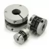 Controlflex Couplings
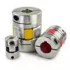 Jaw Couplings
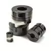 Oldham Couplings
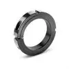 Bearing Locknuts – TCN
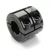 Double Wide Shaft Collars
 Heavy Duty Shaft Collars
 International Series Shaft Collars
 Keyed Shaft Collars
 Mountable Shaft Collars
 Quick Clamping Shaft Collars
 Set Screw Shaft Collars
 Thin Line Shaft Collars
 Threaded Shaft Collars – Pacific International Bearing Products
 Two-Piece Shaft Collars
 Friction Bearing Universal Joints
 Needle Bearing Universal Joints
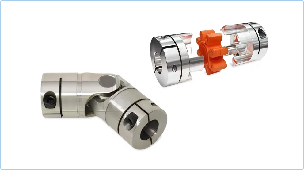
Bearings
Universal Joints vs Other Coupling Options: A Quick Comparison
23 July, 2025
34 min read
Mechanical power transmission often requires connecting shafts that may not be perfectly aligned. Couplings compensate for misalignment, transmit torque, and protect components in automation, robotics, CNC, and industrial drive systems. Pacific International Bearing Sales Inc. (PIB) offers a range of couplings (Ruland, NBK, etc.) suited to different needs. Below we compare universal joints with common flexible coupling types – beam, bellows, disc, Oldham, jaw (spider), and rigid couplings – highlighting their misalignment capabilities, torsional stiffness, torque capacity, backlash, maintenance, speed limits, and best-fit applications.
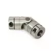
Universal Joints
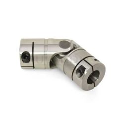
A universal joint consists of two yokes connected by a cross (pin-and-block assembly). Its greatest strength is the ability to handle large angular misalignment – typically up to ~15° per joint (and even 30–40° in special cases). By using two U-joints in series (a double Cardan arrangement), even parallel offsets can be accommodated while maintaining constant velocity output.
- Misalignment: Tolerates far greater angular misalignment than other couplings (often 5× more). Single U-joints commonly operate at 15° misalignment for years, whereas most flexible couplings are limited to ~3°. (Two U-joints can handle combined angles up to ~70° total.)
- Torque & Backlash: Capable of high torque transmission (as seen in vehicle drive shafts). Well-made universal joints have negligible backlash or play – the pin-and-bush design can be very tight-fitting, so they can be used in precision drives. However, a single U-joint does not produce uniform output speed; it causes speed oscillation if operating at an angle (non-constant-velocity coupling). This can introduce vibration at the driven shaft. Using a pair of U-joints (with their yokes phased) cancels out speed fluctuations for smoother motion.
- Stiffness & Maintenance: Universal joints are largely rigid under torsion (little wind-up), but the pivot points mean periodic lubrication is required. They contain moving pins/bearings that wear over time and may introduce slight backlash as they age. Some designs use needle bearings for reduced friction and longer life. Regular grease or boots to retain lubrication can greatly extend life.
- Speed Limits: High-speed operation is acceptable at small angles, but at large misalignment, the speed must be limited. A practical rule is the product of operating angle (degrees) and RPM should stay below ~15,000 for pin-and-block U-joints. For example, ~10° misalignment is safe up to ~1500 RPM; at 25° the speed must stay under ~600 RPM to avoid excessive vibration. Thus, universal joints are often used at moderate speeds or low angles to ensure smooth transmission.
- Applications: Ideal when shafts intersect at significant angles or alignment varies during operation. Common in automotive steering and drive shafts, robotic arms or grippers (where joints pivot), and industrial machinery that requires power transmission through articulated joints. They excel in rugged applications requiring high torque and large misalignment. For instance, PIB offers NBK cross joint couplings (XUT series) that achieve up to 25° angular flexibility with minimal backlash via precision pin-and-bush fits.
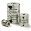
Beam Couplings
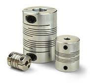
Beam couplings are single-piece flexible couplings cut with one or more helical slots (spiral cuts) along their length. This one-piece “spring” construction gives them flexibility in multiple directions while remaining torsionally connected.
- Misalignment Capacity: Beam couplings accommodate all forms of misalignment (angular, parallel, axial) by flexing along the slits. A typical single-beam coupling might handle around 3° angular and 0.1–0.2 mm parallel offset. Multiple-slot (multiple-beam) designs can allow slightly more misalignment (especially parallel) than single-slit versions. They also allow a bit of axial motion. This flexibility prevents bearing loads from small misalignments.
- Torsional Stiffness & Torque: Beam couplings are moderately compliant – they have lower torsional stiffness compared to bellows or disc couplings. Under high torque or fast reversals, they can wind up (twist) slightly, which may introduce positioning error or “springiness.” Thus, their torque capacity is typically limited (e.g. up to a few tens of N·m for small sizes). They are best for light to medium torque applications. That said, longer multi-beam versions trade even more torsional stiffness for greater misalignment capacity, while short versions are stiffer but with less flexibility.
- Backlash: Beam couplings are zero-backlash; being one solid piece, there is no free play between parts. The clamp or set screw attachment to the shafts can be made tight with no play. This makes them suitable for precision motion control (no lost motion when reversing direction).
- Speed: They have a simple, balanced design and low inertia (often aluminum construction), so they can run at high RPM (often up to 6,000–10,000 RPM) without excessive vibration. Vibration is minimal if the coupling is balanced and misalignment is within allowances. No lubrication or maintenance is needed.
- Pros/Cons: Pros: Simple one-piece construction (nothing to wear or maintain), zero backlash, able to accommodate all 3 misalignment types, lightweight, and inexpensive. They also provide some vibration damping due to their flexibility. Cons: Limited torque and stiffness – too much torque or rapid indexing can cause torsional wind-up. Excess misalignment can cause fatigue failure of the beam over time. They are not as robust for shock loads (could permanently deform or crack under extreme loads or crashes).
- Applications: Widely used for low-to-medium torque duties where some compliance is beneficial – e.g. coupling a motor to a lead screw or encoder, small stepper motor drives, potentiometers, tachometers, pumps, and light industrial automation where misalignments up to a few degrees/0.1 mm need to be absorbed. Their zero backlash makes them suitable for positioning systems (CNC indexers, etc.) as long as the torsional deflection is acceptable in the system’s accuracy budget. Ruland’s multiple-beam couplings (MBS series) and NBK’s slit couplings (MST series) are examples that offer a good balance of flexibility and stiffness for precision motion.
Bellows Couplings
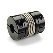
Bellows couplings use thin metallic bellows (usually stainless steel) as the flexible element, bonded or clamped between two end hubs. The bellows – essentially a spring with deep corrugations – provides flexure while transmitting torque with high torsional rigidity.
- Torsional Stiffness & Precision: The metallic bellows have excellent torsional stiffness and zero backlash. Under torque, it twists very little (much less than a beam coupling), making bellows couplings ideal for precision positioning systems that demand minimal wind-up. They are considered zero-backlash couplings – the hubs and bellows are typically joined by rigid bonds or clamps with no play. For example, Ruland’s MBC series bellows couplings are two aluminum hubs fused to a stainless bellows, resulting in a lightweight, high-stiffness coupling with zero backlash. They can maintain precise motion in high-performance servo axes.
- Misalignment Capability: Despite the rigid torsional behavior, the thin bellows walls can flex laterally and angularly. Angular misalignment of around 1–2° is usually allowed, and parallel misalignment on the order of 0.1–0.2 mm (depending on bellows length and diameter) is typical. The bellows’ flexibility results in minimal restoring forces on the shafts within its misalignment range. However, bellows couplings cannot handle as much misalignment as some other flexible couplings – excessive offset can stress or deform the bellows. Extended-length bellows or multi-convolution designs increase allowable misalignment (some designs allow double the misalignment of standard bellows by using more convolutions).
- Torque Capacity: For their size, bellows couplings can transmit moderate to high torque. They come in a range of sizes – smaller units may handle a few N·m, while larger ones (multi-convolution types) can handle hundreds of N·m. They are often rated for higher torque than equivalently sized beam couplings because the all-metal bellows can carry load without significant strain. For instance, NBK’s larger bellows models cover up to ~10 N·m in their standard range, and other brands offer bellows couplings for much higher torques in larger machinery.
- Speed: Bellows couplings generally have a balanced, low-inertia design. They are well-suited to high-speed applications – commonly rated for speeds of 5,000–10,000 RPM or more. The lightweight bellows reduce centrifugal forces. Ruland’s clamp-style bellows couplings, for example, are rated up to 10k RPM while maintaining vibration-free operation.
- Pros/Cons: Pros: Zero backlash and high torsional rigidity – excellent for servo and motion control accuracy. They accommodate misalignment with low bearing loads (the bellows flex easily within limits). Maintenance-free (no moving parts or lubricant). Cons: Sensitive to over-misalignment and shock – a thin bellows can be damaged if misalignment or torque exceeds ratings or if there are severe impact loads. They also tend to be more expensive than simpler couplings due to complex manufacturing.
- Applications: Precision motion systems – e.g. connecting servomotors to ball screws, robotics axes, indexing tables, and any application requiring accurate angular positioning and zero backlash. They are common in CNC machine axes and high-performance linear actuators. Bellows couplings are chosen when you need near-rigid performance in torsion but still want to allow slight misalignment to protect bearings. PIB’s offerings include Ruland MBC-series bellows (for servo motors) and NBK XBW/XBS series, which provide high stiffness and low backlash for precision automation tasks.
Disc Couplings
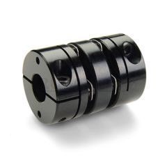
Disc couplings (disk pack couplings) use one or more thin flexible discs (often stainless spring steel) bolted between two hubs (and a center spacer for two-disc designs). The discs flex in plane to accommodate misalignment while transmitting torque through tension/compression of the material.
- Torsional Stiffness & Backlash: Disc couplings are torsionally very stiff (comparable to bellows couplings) and are typically zero-backlash. The disc packs are bolted solidly to the hubs, so there’s no play. Under torque, the discs deform only slightly (they are metal flexures), giving a rigid transmission of rotation. This makes them suitable for precision applications. NBK’s disc couplings, for example, are marketed for high torsional stiffness and zero backlash performance.
- Misalignment: A single-disc design allows primarily angular misalignment (the disc bends into a slight cone shape). A two-disc (double flex) design with a spacer can accommodate parallel misalignment as well, by having each disc flex in opposite angular directions. In general, disc couplings can handle a few degrees of angular misalignment (typically ~1° per disc pack is recommended) and a modest amount of parallel offset (on the order of 0.2–0.5 mm, depending on coupling size and spacer length). They also allow some axial misalignment (end float). Importantly, disc couplings impose low reaction forces on bearings when misaligned, because the discs flex easily in bending. They are often chosen for their combination of high torque and misalignment capacity in larger systems.
- Torque Capacity: The disk pack can support high torque transmission relative to its size – often more than bellows couplings of similar dimensions. Multi-disk couplings in steel can handle hundreds or thousands of Newton-meters. For instance, NBK’s disc coupling lineup covers from ~0.25 N·m up to 280 N·m in standard sizes, and other manufacturers have heavy-duty disk couplings for even higher torques in industrial drive trains. The bolts and disk material define the torque limit; high-strength alloys and multiple disks increase capacity.
- Speed: Disc couplings are generally suitable for moderate to high speeds. They are used on motor and gearbox outputs running at thousands of RPM. The designs are usually balanced (especially the high-performance servo versions) and can operate at 5,000+ RPM safely. Larger power transmission disk couplings (as used in pumps or compressors) can also be balanced for high-speed use. The all-metal construction handles high temperatures and harsh environments as well (no plastic elements).
- Pros/Cons: Pros: High precision (torsionally stiff, no backlash), high torque capacity, and can tolerate misalignment without wear. All-metal, so they can operate in extreme temperatures and have a long life with no maintenance. Cons: They can be relatively bulky and require careful assembly (bolt torques, alignment of disc packs). If overloaded or misaligned beyond limits, the discs can fatigue and crack over time, though this usually gives a predictable lifespan. They have less damping of shock/vibration compared to elastomeric couplings (the metal transmits vibration). Also, the cost is higher than simple couplings.
- Applications: High-performance motion and power transmission – e.g., CNC machine drives, servo gantries, precision indexing tables, and large industrial reducers. They are often found in machine tool spindles and ball screw drives where positioning accuracy is critical. In industrial drives, disc couplings connect motors to pumps, compressors, or generators, offering a balance of misalignment tolerance and strength. PIB can supply disc couplings like Ruland’s servo disc series or NBK’s MD series, which are tailored for servo motors and feature stainless-steel multilayer disks for optimal stiffness and misalignment accommodation.
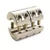
Oldham Couplings
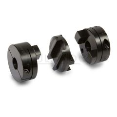
Oldham couplings consist of two hubs with slots (tongues) that engage a center disk (slider) at a 90° orientation. The middle disk, often made of plastic or Delrin, transmits torque by shear between the tongues and simultaneously slides to accommodate misalignment.
- Misalignment Capability: Oldham couplings excel at parallel misalignment. The center disc can slide radially between the hubs, allowing significant offset, often up to 5–15% of the coupling diameter. In practice, values around 0.5 to 1.0 mm (small sizes) and up to 2–3 mm (larger sizes) of parallel misalignment are common. They also accommodate a small amount of angular misalignment (through a slight tilt of the center disc). Standard Oldhams might allow ~1° of angular misalignment before edge interference occurs, but designs with relieved or protruding tenons can allow around 3° of angular misalignment. NBK’s Oldham couplings, for example, use a protruded disk (MOL series) that supports the hubs and permits up to 3° angular misalignment with minimal bending moment on the shafts. (By contrast, Oldhams without this feature bind beyond ~1° and cause bending loads.) Overall, Oldham’s have high misalignment tolerance, especially for parallel offsets – they correct lateral shaft misalignment better than most other coupling types.
- Torque & Stiffness: The torque is transmitted through the shear of the center disc and the mating keys. This design has moderate torque capacity – suitable for many motor applications, but generally less than an equivalently sized rigid or disc coupling. The plastic (or metal) slider can be the weak link in terms of strength. For example, standard Oldhams in small sizes handle from <1 N·m up to tens of N·m in larger sizes (NBK’s range goes up to ~176 N·m). Torsional stiffness is low to moderate, since the disk is slightly elastic in shear. This provides a cushioning effect (which can protect against shocks) but also means some wind-up under load. Oldhams are not as torsionally rigid as bellows or disc couplings.
- Backlash: A key advantage is that Oldham couplings can be designed for zero backlash. In high-performance versions, the center disk’s tenons are a tight press-fit in the hub slots with slight preload, eliminating play (while still allowing sliding). This ensures no lost motion in reversing direction. However, in standard industrial Oldhams, there might be a small gap for ease of assembly, resulting in a minute backlash. Over time, as the disk wears, some backlash can develop. For precision applications, zero-backlash Oldham couplings (with fully constrained sliders or flexible inserts) are available, combining precision with misalignment capability. Additionally, the plastic middle element electrically isolates the two shafts, which can be beneficial (prevents electrical coupling and galvanic corrosion between shafts).
- Maintenance & Failure Mode: Oldham center disks are a wearing part. As the disk slides under misalignment, its tenons rub in the hub grooves. This sliding is where energy is dissipated (which also means Oldhams can tolerate misalignment without large reaction forces – the slip relieves stress). Over time, the disk will wear and require replacement (a clear sign is increasing backlash or slippage). Fortunately, replacing the disk is easy and inexpensive compared to replacing the whole coupling. Oldhams generally don’t require lubrication; the disks are often engineered plastic with low friction. They run reasonably cool at moderate speeds, though at very high RPM the centrifugal forces on the floating disk and friction can cause heating – hence Oldhams usually have an upper speed limit (~3,000–4,000 RPM is common). Another note: Oldham couplings are not fail-safe – if the center disk fails (cracks or shears), the coupling will lose torque transmission entirely (the hubs will spin independently). This contrasts with jaw couplings, which have interlocking hubs (fail-safe).
- Pros/Cons: Pros: Excellent for correcting parallel misalignment; low reaction forces on bearings (the sliding action avoids high bending loads). They can be zero-backlash and provide some shock absorption via the plastic element. They’re also simple and compact, and by mixing disk materials (e.g, softer plastic) they can reduce vibration. Cons: Periodic maintenance (disk replacement) is needed in high-duty cycles. Not suited for very high speeds or very high torques. They introduce a slight elasticity in the drive (not as rigid as one-piece couplings). Backlash can increase as they wear. And, as mentioned, if overloaded, the disk can fail (though it usually wears gradually rather than suddenly catastrophic failure).
- Applications: Oldham couplings are a great general-purpose solution in motion control when shafts are misaligned. Commonly found in stepper motor and servo motor connections to lead screws, pumps, gearboxes, or encoders where alignment isn’t perfect. For example, in a CNC machine, a stepper motor can be connected to a ball screw with an Oldham coupling to forgive slight installation misalignment. They are also used in X-Y positioning stages, conveyor drives, and assembly machinery. NBK’s Oldham couplings (MOL, MOC series) are used in semiconductor equipment for their precision and misalignment accommodation, and Ruland’s Oldham couplings (which use replaceable disks) are popular in packaging and printing machines. When designers need lateral flexibility and moderate torsional damping without sacrificing all precision, Oldhams are often the top choice.
Jaw Couplings
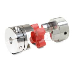
Jaw couplings consist of two metal hubs with interlocking jaws (usually 3 jaws on each hub) that mesh together, with an elastomer spider insert between them. The spider’s legs fit between the jaws of each hub. This design provides a mix of flexibility and damping (from the elastomer) with fail-safe torque transmission (if the spider fails, the metal jaws will contact).
- Misalignment & Damping: Jaw/spider couplings accommodate moderate misalignment in all forms: typically up to ~1° of angular misalignment and around 0.1–0.2 mm of parallel offset (varies with spider elasticity and coupling size). The elastomer spider compresses to allow slight angular and parallel displacement. It can also compress axially, which is useful for damping shock loads. The defining feature of jaw couplings is their vibration and shock absorption. The polyurethane (or rubber) spider element absorbs impulse loads and torsional vibrations, protecting connected equipment. This makes jaw couplings well-suited for systems where moderate cushioning is beneficial (e.g., protecting a servo gearbox from sudden impacts). The trade-off is that they are not as precision-rigid as all-metal couplings.
- Torsional Stiffness: The torsional stiffness of a jaw coupling depends on the durometer (hardness) of the spider. A softer spider (lower durometer) yields more damping and forgiveness at the cost of more torsional deflection (softer = more twist under load). A harder spider increases stiffness and torque capacity but transmits more vibration. Manufacturers often offer spiders in different hardness levels (e.g., “soft” 80 Shore A vs. “hard” 98 Shore A) to let designers tune the coupling’s performance. With the hardest spiders, a jaw coupling becomes fairly stiff torsionally, though still not as stiff as a one-piece metal coupling. Typical torsional wind-up might be a few degrees at full torque for softer spiders, and less than a degree for hard spiders (depending on coupling size).
- Torque Capacity: Jaw couplings can transmit high torque for their size, especially with stiff spiders. For example, jaw couplings in the 20–30 mm OD range can handle dozens of N·m, and larger versions can go into the hundreds of N·m (e.g., NBK’s jaw range goes up to ~560 N·m in the largest size). The metal hubs carry the load through the spider via compression. One advantage is that if the spider is overloaded to failure, the metal jaws of the two hubs will interlock and continue to transmit torque (albeit with metal-to-metal contact). This fail-safe design means the machine won’t lose drive suddenly; it can be shut down gracefully for maintenance. (In normal operation, however, the metal jaws do not touch – there is a gap filled by the spider, ensuring the coupling remains elastic and with electrical isolation between hubs.)
- Backlash: A standard straight-jaw coupling (with a loosely fitting spider) can exhibit a small amount of backlash because the spider isn’t preloaded – the spider legs might not perfectly fill the jaw gaps, leaving slight clearance. However, zero-backlash jaw couplings are available and widely used in motion control. These use curved jaw hubs and a preloaded spider. The spider is slightly oversized and press-fit into the jaws, eliminating any free play. Ruland’s zero-backlash curved jaw couplings (Spider-type) are an example: the curved profile and squeezing of the spider ensure no backlash while still allowing flex. The curved jaws concentrate forces centrally and avoid edge contact, which improves spider life and consistent stiffness. In summary, with the correct spider, jaw couplings can be run truly backlash-free, making them compatible with servo positioning systems. It’s important to select the right spider hardness and ensure it’s rated for zero-backlash operation (some manufacturers specify torque limits for zero-backlash performance of spiders).
- Speed: Jaw couplings can handle moderate to high speeds. With a properly balanced hub and spider, they commonly run up to ~8,000 RPM or more. The main limitation at high speed is the spider material (centrifugal forces can cause deformation if the design isn’t balanced, and heat buildup in the elastomer can occur at very high RPMs). For most servo motor applications (which might run 3,000–6,000 RPM), a quality jaw coupling poses no issue. They require no lubrication and little maintenance (just periodic inspection of the spider for wear/cracks, especially in high temperature or chemical environments that might degrade the elastomer).
- Pros/Cons: Pros: Versatile and forgiving. They handle misalignment, cushion shocks, dampen vibration, and can be zero-backlash when designed properly. They are fail-safe (continued drive on spider failure), which is reassuring for critical applications. Installation is easy (slip the spider in, no intricate assembly). They also tolerate a bit of misalignment without huge bearing loads due to the elastomer’s give. Cons: The elastomer limits temperature range (usually up to ~80°C or a bit higher for advanced materials) and can degrade in harsh chemicals. Torsional stiffness is lower than all-metal couplings, so in highly dynamic systems (fast reversing servos, high precision positioning), the slight squish can affect control tuning or accuracy. Also, spiders will eventually age and may need replacement (though they often last many years in well-aligned systems). If used in a high-precision servo system, one must ensure the spider’s compliance is accounted for in the control system (it can sometimes cause a resonance if too soft).
- Applications: Jaw/spider couplings are extremely common in general industrial power transmission and motion control. They are used on pumps, compressors, conveyor drives, mixers – anywhere you want to protect the motor and driven equipment from shock loads. In automation, they connect servo and stepper motors to ball screws, lead screws, gearboxes, and indexers, providing a good balance of zero backlash (if using a press-fit spider) and vibration damping. They are also popular in robotics and CNC machines for axes that don’t demand ultra-high torsional rigidity but do benefit from some vibration absorption (for example, a CNC router’s spindle drive or a rotary table). PIB offers jaw couplings from Ruland (e.g., the L-Series and SPider Jaw (MSJ) series with different durometer spiders) as well as NBK’s MJC series. These allow designers to select spider hardness to tune the system’s response. In summary, jaw couplings are the go-to for reliable, flexible couplings that cover misalignment and shock mitigation in one package.
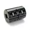
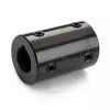
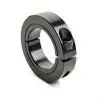
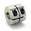
Rigid Couplings
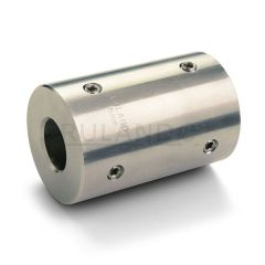
Rigid couplings are solid connectors (one-piece or two-piece clamps) that do not allow misalignment. They simply lock two shafts together, end-to-end, creating what is effectively a single continuous shaft. While not “flexible” couplings, they are worth including for comparison as the extreme case of zero flexibility.
- Misalignment: None. Rigid couplings demand perfect shaft alignment – any misalignment will result in large forces, binding, or failure of components. In use, rigid couplings are only suitable when the shafts are very accurately aligned (or where the system is built such that misalignment is virtually zero or can be neglected). They transmit all misalignment as potentially destructive stress to bearings or shafts, so they are only used in the absence of misalignment or when other components (like flexible mounts or self-aligning bearings) accommodate it.
- Torsional Stiffness & Torque: A rigid coupling has maximal torsional stiffness – essentially infinite for practical purposes (no twist other than the material’s own tiny elastic deformation). This means no wind-up, no lost motion, and zero backlash by design. It transmits torque as if the two shafts were one. As a result, it can handle very high torque, often limited only by the coupling’s material strength and the shaft/hub interface (keys or clamp friction). For example, a steel rigid clamp coupling can transmit hundreds or thousands of N·m if sized appropriately, far exceeding the torque of equivalently sized flexible couplings. Ruland’s MCLX series one-piece rigid couplings, for instance, have precision-honed bores to ensure exact fit and collinearity – this guarantees they do not introduce misalignment or vibration and can transmit the full rated torque of the shafts without slippage.
- Backlash: Zero. Since it is a solid connection, there’s no backlash at all (and no elastic element to introduce micro-slippage). This makes rigid couplings ideal for high-precision motion where even the slight compliance of a flexible coupling is not tolerable – but again, only if alignment can be guaranteed by other means.
- Speed: Rigid couplings can run at extremely high speeds (they are essentially a balanced chunk of metal when properly machined). There are high-speed precision, rigid couplings used in spindle applications. The only concern is balance and the effect of any tiny misalignment at high RPM (because even 0.05 mm misalignment at 10,000 RPM will cause vibration). But the coupling itself doesn’t impose a speed limit as long as it’s balanced – it’s only limited by the strength of screws and integrity of clamping at those speeds. Many rigid couplings are short, making them inherently balanced. For safety, designers ensure rigid couplings are well-secured (using proper clamp screw torques, possibly keyways or additional retention like vibration-resistant screws if needed). Ruland uses Nypatch anti-vibration coating on clamp screws of their rigid couplings to prevent loosening.
- Maintenance: Not much – no moving parts. Just periodically check that screws remain tight (since any loosening could introduce play or misalignment). No lubrication needed. Rigid couplings made of stainless steel or alloy steel are robust and durable indefinitely under proper use.
- Use Cases – Pros/Cons: Pros: Absolute rigidity and accuracy in torque transfer. Simple and strong. If you have two perfectly aligned shaft ends, a rigid coupling is the most compact, no-fuss way to join them. Cons: Any misalignment at all will cause problems, from minor stress to major failure. Even thermal expansion that causes slight shifts can stress rigid couplings. Therefore, their use is limited to when you can ensure alignment (e.g., a motor bolted to a gearbox flange with dowel pins to maintain alignment might use a rigid coupling internally). They also do not absorb any shock or vibration – they transmit it all.
- Applications: Generally used in precision equipment where alignment is controlled by design. Examples: connecting two shafts in a fixed assembly (like two sections of a linear actuator drive shaft) or extending a shaft. In laboratory or test machines, sometimes rigid couplings are used for temporary setups where flexibility isn’t needed. Another use is in shaft collars and adapters (rigid couplings can double as shaft adapters between different diameters, since they can be machined with different bore sizes on each end). PIB provides one-piece and two-piece rigid couplings (such as Ruland’s clamp-type rigid couplings, e.g., MCLX series) that are machined to high precision – the bores are collinear and perfectly aligned so they do not introduce misalignment or vibration on their own. These are employed in systems like encoder mounts, lead screw extensions, or servo motor/gearbox connections where the mounting is so tight that a flexible element is unnecessary. In summary, rigid couplings are only chosen when misalignment is virtually zero and maximum stiffness or simplicity is paramount.
Summary Comparison Table
The table below summarizes key characteristics of universal joints vs. various coupling types, to aid in selecting the optimal solution:
| Coupling Type | Max Angular Misalignment | Max Parallel Misalignment | Backlash | Torsional Stiffness | Typical Torque Capacity | Typical Speed Range | Best-Fit Applications |
| Universal Joint | Very high (15° per joint, up to 30°+ total) | Minimal (requires two joints for offset) | None (if precision joint) | High (nearly rigid) | Very high (can handle heavy loads) | Low–Moderate (limited by angle: e.g. 25° ≤600 RPM) | Large misalignment shafts; steering columns, articulated drives |
| Beam Coupling | Moderate (~3–5°) | Low (~0.1–0.2 mm)] | Zero | Low–Medium (elastic wind-up under load) | Low–Medium (a few N·m to ~35 N·m) | High (up to ~6,000–10,000 RPM) | Encoders, small pumps, light-duty motion where some compliance is OK. |
| Bellows Coupling | Low (~1°, maybe 2° max) | Very low (~0.1 mm) | Zero | Very high (torsionally stiff) | Medium–High (5 N·m to 100+ N·m) | High (balanced for ~10,000 RPM) | Precision servo drives, CNC axes – needing zero backlash & rigidity. |
| Disc Coupling | Low–Moderate (~1° per disc pack) | Low–Moderate (~0.2–0.5 mm) | Zero | Very high (stiff, like bellows) | High (up to hundreds of N·m) | High (5,000+ RPM, if balanced) | High-torque precision systems, servo & spindle drives, pumps. |
| Oldham Coupling | Moderate (∼3° with protruding disk) | High (1–2+ mm) | Zero (with preload) or Very low | Low–Medium (spider in shear) | Medium (few to tens of N·m) | Moderate (≤3,000 RPM typically) | Offset shafts in motion control, stepper motor drives – misalignment forgiving. |
| Jaw (Spider) | Moderate (~1°) | Low (~0.1–0.2 mm) | Zero (curved; preloaded)or slight (std.) | Medium (tunable via spider durometer) | Medium–High (10 N·m up to 100+ N·m) | Moderate–High (up to ~8,000 RPM) | General-purpose power transmission, servo/stepper coupling with vibration damping. |
| Rigid Coupling | None (0°) | None (0 mm) | Zero | Maximum (completely rigid) | Very high (shaft will fail before coupling) | Very high (limited only by balance) | Perfectly aligned shafts, high precision or test setups, and shaft integration. |
Notes: Universal joints are unique in providing a huge angular offset but are a separate class of joint (used in pairs for constant velocity). Among “flexible couplings,” Oldham has the greatest parallel offset ability, while bellows and disc offer the best precision (stiffness and zero backlash). Beam and jaw couplings fill the middle ground – easier to use and good for general purposes. Rigid couplings are only for when you truly have no misalignment. Always consider the specific model’s ratings (misalignment and torque) and check manufacturer data (e.g., Ruland, NBK specs) for the exact numbers, as designs vary. For example, Ruland’s MCLX rigid couplings ensure no added misalignment by honing bore collinearity, Ruland bellows (MBC) achieve high speed and stiffness, and Ruland zero-backlash jaw couplings use a preloaded spider to eliminate play. NBK’s offerings (e.g., XUT cross joints, MCJ jaw couplings, MOL Oldhams) further allow engineers to tailor coupling choice to their system’s alignment, torque, and dynamic requirements.
Conclusion
Choosing the right coupling is a balance of the required misalignment compensation, torsional rigidity, torque capacity, and vibration/backlash considerations for your system. Universal joints stand out for large misalignment angles, whereas flexible couplings (beam, bellows, disc, Oldham, jaw) each offer a unique mix of flexibility and stiffness:
- Use universal joints when shafts meet at significant angles or misalignment varies during operation – they handle the angles others can’t (with the caveat of speed limitations and needing lubrication).
- Use beam couplings for light-duty, zero-backlash needs with moderate misalignment – they’re simple and economical for small equipment and instrumentation.
- Use bellows or disc couplings for high-precision motion control – they maximize torsional stiffness and minimize backlash, at the cost of lower misalignment range (best in well-aligned, servo-grade systems).
- Use Oldham couplings for applications with notable parallel misalignment or where electrical isolation is needed – they protect bearings from offset errors and are easy to service (replace the insert).
- Use jaw (spider) couplings for a versatile solution that can handle some misalignment and shock, especially in general industrial drives and servo systems where a bit of compliance is beneficial (and zero backlash versions are available for precision).
- Use rigid couplings only if you have virtually no misalignment and require the utmost rigidity – essentially treating two shafts as one continuous shaft.
By understanding these trade-offs and referring to technical specs (such as those from PIB’s partner brands like Ruland – e.g., MCLX, MBC, MSJ series – and NBK’s coupling catalog), mechanical engineers and system designers can confidently select the optimal coupling to ensure smooth, accurate, and reliable operation of their automation, robotics, or industrial drive systems. The quick comparison above should serve as a starting guide in that decision process, ensuring the chosen coupling delivers the needed performance while accommodating the real-world misalignments in your machine.
Please contact us at [email protected] or visit us at www.pibsales.com. Or call us Toll Free at 1-800-228-8895.