Your cart is empty
 Short Rigid Couplings
 Controlflex Couplings
 Jaw Couplings
 Oldham Couplings
 Bearing Locknuts – TCN
 Double Wide Shaft Collars
 Heavy Duty Shaft Collars
 International Series Shaft Collars
 Keyed Shaft Collars
 Mountable Shaft Collars
 Quick Clamping Shaft Collars
 Set Screw Shaft Collars
 Thin Line Shaft Collars
 Threaded Shaft Collars – Pacific International Bearing Products
 Two-Piece Shaft Collars
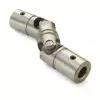 Friction Bearing Universal Joints
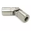 Needle Bearing Universal Joints
Robotics
Best Practices for Designing Motion Components in Humanoids
27 February, 2025
20 min read
Pacific International Bearing along with the Schaeffler Corporation, one of the largest bearing companies in the world, has established a huge footprint in robotics and AI.

The proper design of motion components determine how well humanoid robots mimic human movement. Parts like actuators, bearings, and bushings turn robotic concepts into functional systems that move naturally.
Advances in materials, AI, and custom engineering have improved their performance, flexibility, and lifespan.
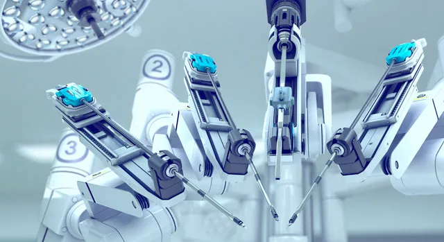
Today, humanoid robots are no longer just experimental; they’re being used for real-world applications. Above in Fig 1. An Agility Robotics’ Digit humanoid robot at work in a GXO Logistics facility near Atlanta. Interestingly, Schaeffler has signed an agreement with Agility Robotics to purchase its humanoid robots for use across Schaeffler’s global plant network.
PIB Sales offers precise motion solutions designed for demanding robotic needs. From corrosion-resistant bearings to maintenance-free options, our products meet the challenges of complex systems.
Motion Principles in Humanoid Robots: Bearings, Efficiency, and Stability
Humanoid robots achieve human-like motion through careful mechanical design and control of their joints. This report focuses on the mechanical motion principles, especially the role of bearings in joints.
Bearing Types in Humanoid Robot Joints
Bearings are crucial in humanoid robot joints to reduce friction and support loads, enabling smooth and precise movement. Different joint actuators (rotational or linear) use specific bearing types chosen for their load capacity, compactness, and ability to handle particular force directions. Table 1 summarizes key bearing types commonly used in humanoid robots, their typical applications, and their benefits:
| Bearing type | Application in robot | Benefits/characteristics |
| Crossed Roller Bearing | Rotary joints (e.g. major arm/leg axes, actuator outputs) | Cylindrical rollers arranged crosswise can support radial, axial (both directions), and moment loads simultaneously. High rigidity and minimal play ensure precise joint motion. Low friction improves efficiency. |
| Four-Point Contact Ball | Rotary joints (actuator inputs, combined-load joints) | Spherical balls contact races at four points, handling combined radial and axial loads in both directions. Compact and cost-effective design with split ring options for larger contact angles (higher axial capacity). |
| Angular Contact Ball | High-load joints (used in pairs for joints like shoulders or wrists) | High axial load capacity, especially when used back-to-back or face-to-face to take thrust in both directions. Greater contact angle yields higher axial load support. Common in precision joints requiring stiffness. |
| Flexible Ball Bearing | Harmonic drive wave generators (in actuators for hips, knees) | Very thin-section ball bearing that flexes into an oval when the elliptical cam rotates. Allows harmonic drives to transmit motion with zero backlash. Supports radial and limited axial loads while conforming to drive deformation. |
| Deep Groove Ball | Linear actuators, general rotary joints | Versatile and simple design for primarily radial loads (with limited axial load). Durable and easy to maintain, used where moderate loads and high speeds are needed (e.g. small motors, sliders). |
| Spherical Plain Bearing (Rod-End) | Linkages and misalignment points (e.g. ankle, hip link rods) | Spherical inner ring that can tilt inside a cylindrical outer ring, accommodating misalignment. Used in rod ends and “dog-bone” linkages to allow multi-axis rotation and oscillation under high radial and axial loads. |
| Plain Bearing (Bushing) | Compact joints in tight spaces (fingers, wrist) | Sleeve bearing with low-friction material (often self-lubricating). Used where rolling bearings can’t fit. Reduces friction and wear, quiet operation, but handles lower loads. |
These bearing selections ensure the robot’s joints can handle the required loads and motions. For example, crossed roller bearings often serve as output bearings in high-torque actuators because of their rigidity and ability to take complex loads, whereas four-point contact bearings might be used as input bearings where space is limited but combined loads occur. By choosing the appropriate bearing type for each joint, designers achieve smooth rotation with minimal friction, high accuracy, and durability in the robot’s movements.
Load Distribution and Stress in Bearing-Supported Joints
Humanoid robot joints frequently use multiple bearings in a single joint assembly (e.g. a pair of bearings separated along a shaft) to better distribute forces. Understanding how loads are shared between bearings is important for the structural integrity and longevity of the joint. Bearings in a joint may experience different types of loads: radial (perpendicular to the shaft), axial (along the shaft, i.e. thrust), and moment (bending or tilting forces that create a moment). High-performance robots often encounter combined loads; for instance, a robot’s knee joint under load while moving can impose radial load from the weight and axial load from any tension in actuators simultaneously.
Load distribution example: Consider a simple joint with two support bearings (bearing A and B) a distance L apart, carrying a downward load F (e.g. from an arm or leg link). If the load is located closer to bearing A (at a distance aaa from A, so b=L−ab = L – ab=L−a from B), static equilibrium gives the reaction forces:
- FA=F×bL
- FB=F×aL
This means the bearing nearer to the load carries more of the force. Engineers must ensure each bearing’s reaction FA,FB does not exceed its rated load capacity. Manufacturers specify load ratings (e.g. a typical ball bearing might support ~5,000 N radial load and ~2,500 N axial load), which are based on material stress limits and fatigue life calculations. The bearing stress (contact stress) within the raceway is localized and high, so keeping loads within allowable limits prevents excessive contact pressure that could lead to material fatigue or brinelling.
To evaluate joint safety, engineers calculate the bearing stress or use supplier-provided dynamic load ratings. A simplified stress check for a bearing pin or shaft in a joint is σ=FA (force divided by projected area) as a first approximation of bearing pressure. In reality, rolling element bearings require Hertzian contact stress formulas for precise results, but typically one uses the bearing’s rated load. For example, safety factors are applied so that the expected maximum load on a bearing is a fraction of the bearing’s limit to ensure a long life under repetitive motion.
Properly distributing loads across bearings also increases the joint’s stiffness and stability. A pair of angular contact bearings, for instance, is often arranged back-to-back at a joint so that one handles thrust in one direction and the other takes the opposite thrust, sharing the axial stress and maintaining alignment. By spreading out forces and moments, the joint minimizes bending of the shaft and uneven wear on bearings. This results in smoother motion and reliable operation even under heavy or impact loading.
Friction and Efficiency in Robot Joints
Minimizing friction in joints is essential for energy-efficient and precise motion. Bearings are designed to significantly reduce friction between moving parts compared to an unlubricated sliding contact. The use of rolling elements (balls, rollers) creates only small contact areas, which drastically lowers the friction coefficient. Typical sliding friction coefficients for metal on metal might be μ≈0.2 \mu \approx 0.2μ≈0.2 (or higher without lubrication), whereas a good ball bearing can have an effective friction coefficient on the order of μ≈0.001 \mu \approx 0.001μ≈0.001–0.005 under load. Lower friction means less energy lost as heat and more efficient transmission of power from motors to the limbs.
Friction and power loss: A useful formula relating bearing friction to energy loss is:
Ploss= Tf×ω,
where TfT_fTf is the frictional torque in the bearing and ω\omegaω is the angular speed (in radians/sec). This equation gives the power (in watts) being dissipated as heat due to friction. Engineers strive to keep TfT_fTf low through proper bearing selection and lubrication, because any power lost here reduces the overall efficiency of the robot’s actuation. For example, if a joint motor delivers 50 Nm of torque and 2 Nm is lost to friction in bearings and seals, at an angular speed of 1 rad/s the power loss is 2×1=22 \times 1 = 22×1=2 W. Over many joints and continuous operation, these losses add up, draining batteries and heating up actuators.
Several factors influence bearing friction torque:
- Bearing type & design: Rolling bearings (balls or rollers) generally have lower friction than plain bushings. Within rolling bearings, designs with separators (cages) to prevent rubbing between elements further reduce friction. For instance, crossed roller bearings with a cage have minimal difference between static and dynamic friction torque, preventing stick-slip and saving energy.
- Load on the bearing: Higher loads increase deformation and contact friction. However, good design (e.g. larger diameter or more rolling elements) can spread the load to keep friction increases moderate.
- Lubrication: Proper lubrication is crucial. A thin film of grease or oil reduces metal-to-metal contact, lowering the coefficient of friction μ\muμ. The frictional force is Ff= μFn (where FnF_nFn is the normal load on the contact), and lubrication effectively lowers μ\muμ. Regular maintenance ensures lubrication is effective and contaminants are removed, which keeps friction torque low.
- Speed and viscous effects: At higher speeds, lubricant viscosity and drag can contribute to friction (fluid friction in the grease). Bearing manufacturers provide friction torque vs. speed characteristics to predict this. Generally, well-designed bearings keep friction low over the operating speed range.
Efficiency: By reducing friction, bearings improve the mechanical efficiency of each joint. The efficiency η\etaη of power transmission through a bearing-supported joint can be roughly estimated by η= Pout Pin = 1 – Ploss Pin
For precision robots, energy optimization is critical: less energy wasted as heat means more battery life and cooler operation. This also ties into thermal management – high friction can cause heat buildup, potentially affecting sensor and motor performance. Thus, bearings not only enable smooth motion but also play a direct role in the robot’s energy economy and longevity.
Stability and Balance Considerations
In addition to the mechanical components inside joints, humanoid robots must obey physical stability criteria to avoid falling. Stability in a static sense means the robot’s center of mass (CoM) must project onto the area of support (the feet) – otherwise gravity will create a tipping moment. The support base (often called the support polygon, which for a biped is the convex area covering the feet contact) defines the region in which the CoM must lie for static equilibrium. If the CoM moves outside this support area, the robot will start to tip because no restoring ground reaction force can counteract the moment caused by gravity about the edge of the foot.
A simple static stability criterion: for an object of weight W=mgW = mgW=mg (mass times gravity) on a horizontal surface, the normal reaction forces from the ground adjust such that their resultant passes through the CoM if it’s within the footprint. If the CoM is at a horizontal distance xxx outside the footprint edge, a restoring moment cannot be generated – leading to rotation (tipping). This is why humanoid robots carefully control their posture to keep the Center of Gravity (CoG) above the support base during standing or slow movements.
By refining the mechanical design with high-quality bearings and applying fundamental formulas, humanoid robot engineers achieve human-like motion that is smooth, efficient, and stable. Key bearing types (crossed rollers, angular contact, four-point contact, etc.) are selected to support the unique load profiles of each joint, as summarized in the table, providing the necessary combination of load capacity, precision, and low friction. Through proper load distribution among bearings and careful stress analysis, joints are built robustly to handle forces without excess deformation or wear. Friction optimization via bearings and lubrication ensures that energy from actuators is used productively for movement rather than wasted as heat, directly improving the robot’s efficiency and battery life. Finally, stability principles like maintaining the center of mass over the support polygon and controlling the Zero Moment Point are applied to guarantee that the robot can balance and walk reliably.
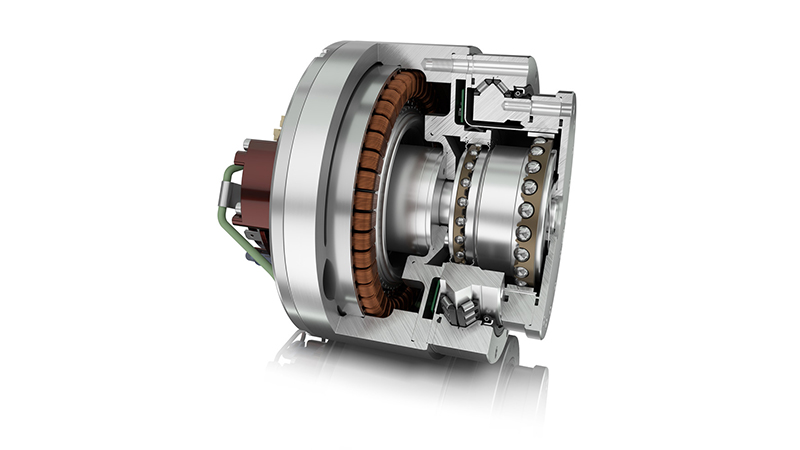
Crossed Roller Bearings
In humanoid robots, joints such as hips, knees, shoulders, and wrists must handle complex loads while maintaining rotational accuracy. These joints experience forces in multiple directions — radial (perpendicular to the shaft), axial (along the shaft), and moment (torque due to off-axis loading). Conventional ball bearings often fail to support all these forces efficiently, leading to misalignment, increased friction, and mechanical wear.
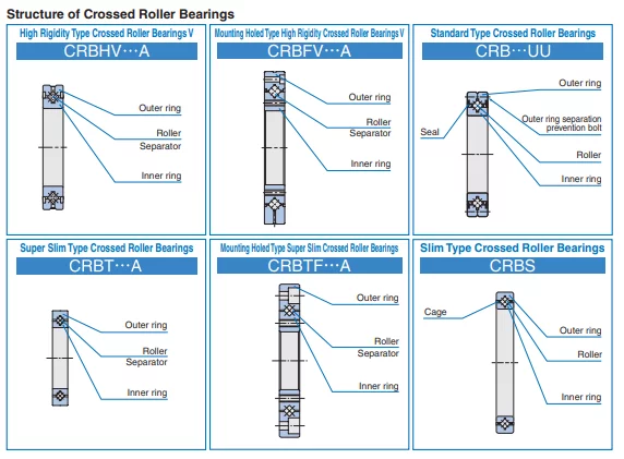
This is where crossed roller bearings (CRBs) from IKO excel. Unlike standard ball bearings, CRBs use alternating cylindrical rollers positioned at 90-degree angles, allowing them to support all three types of loads simultaneously while maintaining compact dimensions.
For example, IKO CRBF8022ADU, a widely used crossed roller bearing in humanoid robotics, offers high stiffness and minimal play, making it ideal for robotic hip and knee joints, where both rotational accuracy and load-bearing capacity are essential. Similarly, the IKO CRBH Series, which features an ultra-thin profile, is frequently integrated into shoulder actuators, where space constraints demand a compact yet rigid bearing.
The engineering advantages of using IKO CRB bearings in humanoid robots include:
- Reduced backlash — ensuring joints move without unwanted clearance, critical for fine motor control.
- Higher moment-load resistance — preventing bending or misalignment under dynamic stress.
- Minimal friction — allowing efficient torque transmission from actuators, leading to smoother movement.
- Long service life — ensuring reliability over prolonged operational cycles, reducing maintenance needs.
In high-speed humanoid robots, such as Boston Dynamics’ Atlas, advanced crossed roller bearings are deployed in load-intensive hip and knee joints, where their rigid construction prevents unwanted vibrations while enabling rapid, precise movements.
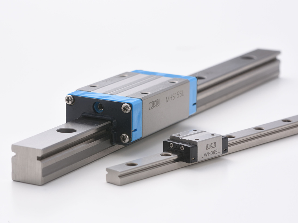
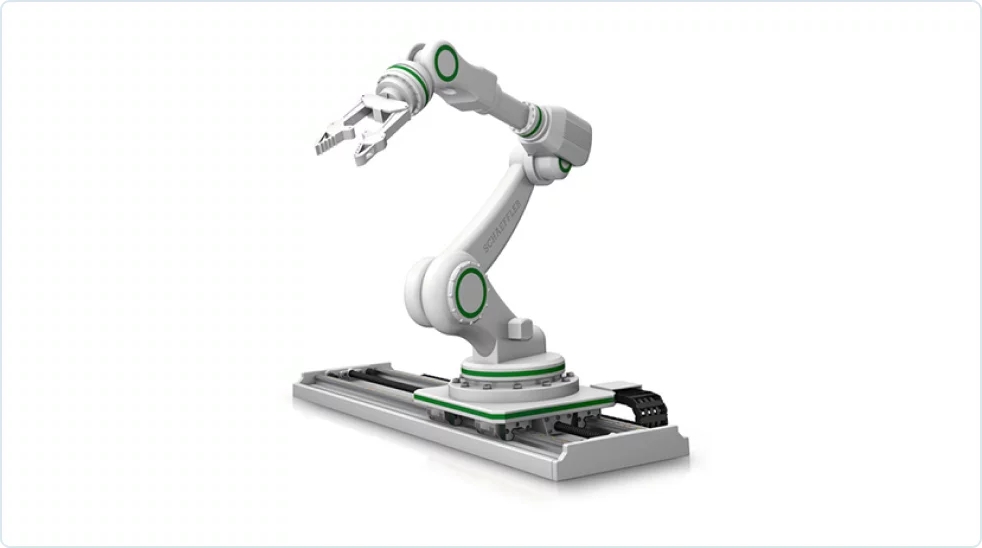
Linear Motion Rolling Guides
Humanoid robots require both rotational and linear motion to mimic human dexterity. While crossed roller bearings manage rotational articulation, linear motion rolling guides are vital for components that require translational movement, such as torso lifts, arm extensions, and precision end-effectors.
IKO Bearings manufactures high-precision linear motion rolling guides, such as the ML Series, which are specifically designed for miniature robotic applications. With a recirculating ball-type mechanism, these guides enable humanoid robots to achieve smooth, controlled linear motion with minimal resistance.
For example, in robotic grippers and dexterous hand assemblies, IKO ML9 Series rolling guides are implemented to facilitate precise grasping and object manipulation. These guides allow robotic fingers to close and open seamlessly, applying just the right amount of force without damaging delicate objects.
In larger humanoid assemblies, such as torso extensions or telescoping robotic limbs, the IKO LWH Series provides enhanced structural rigidity, ensuring linear motion remains stable under variable loads. These guides are frequently incorporated into robots designed for industrial and logistics applications, where humanoid systems need to reach high shelves or extend their field of vision.
The benefits of IKO’s linear motion rolling guides in humanoid robots include:
- Low-friction movement, improving energy efficiency and reducing heat buildup.
- High-load capacity, allowing humanoid robots to execute forceful pushing or lifting actions without excessive wear.
- Long stroke precision, ensuring repeatable, accurate movement over extended use cycles.
A practical implementation of IKO ML and LWH rolling guides can be observed in NASA’s Valkyrie humanoid, where these components support torso articulation and tool-handling arms, allowing the robot to extend its operational range while maintaining precise control over its linear motion.
Spherical Plain Bearings: Enhancing Stability and Multi-Directional Motion
One of the most challenging aspects of humanoid robot design is stability — particularly in feet, ankles, and waist joints, which must continuously adjust to external forces while maintaining balance. Traditional rotary bearings often fail to account for multidirectional flexibility, resulting in joint stiffness and reduced adaptability in dynamic environments.
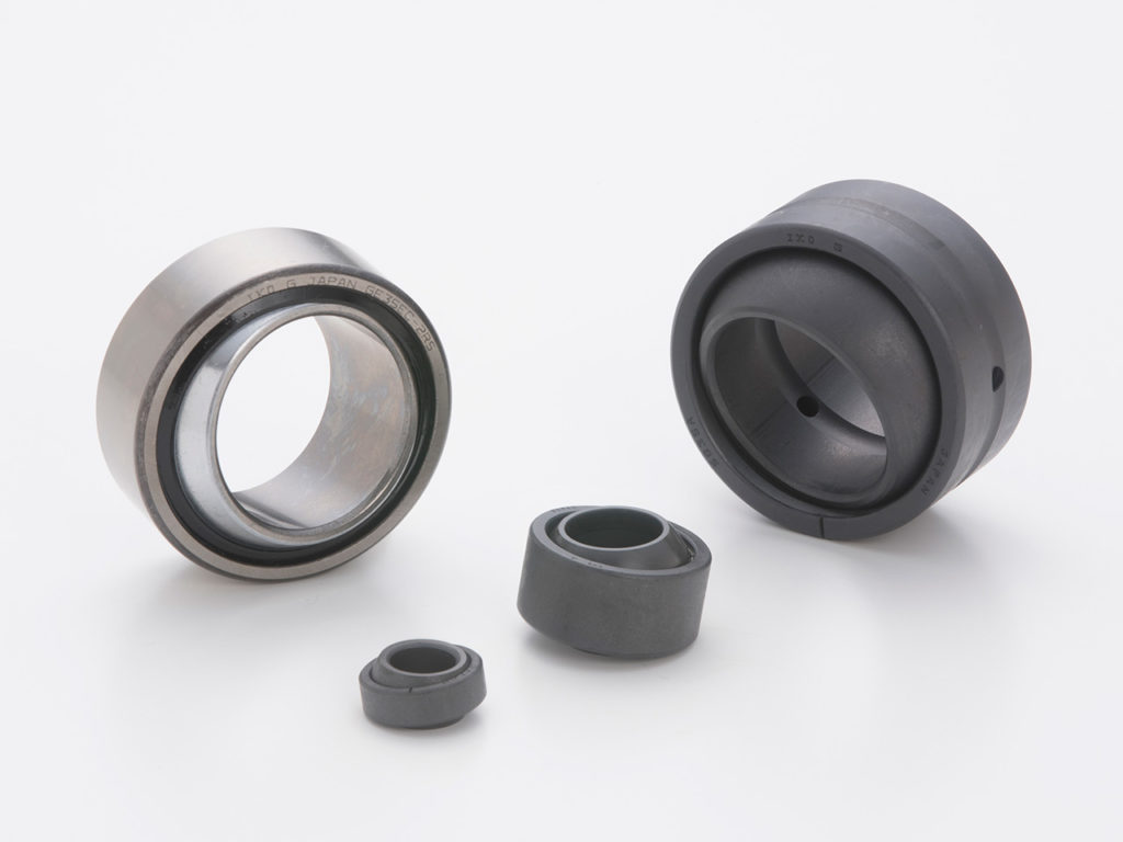
To address this, IKO Bearings provides high-load spherical plain bearings (bushings), such as the SB and GE Series, which allow multi-axis pivoting motion without sacrificing strength. Unlike conventional rolling bearings, these components feature a spherical inner ring that tilts inside a cylindrical outer ring, allowing humanoid robots to simulate natural human joint behavior.
A key application of IKO spherical plain bearings is in humanoid ankle assemblies, where dynamic weight shifts require fluid multi-axis articulation. For example, in bipedal humanoid robots designed for terrain adaptation, IKO SB2022-2RS bearings are commonly used to provide enhanced pivoting capability, allowing robots to adjust foot positioning dynamically.
The engineering advantages of IKO spherical plain bearings in humanoid robots include:
- Shock absorption, reducing impact loads that could damage other mechanical components.
- Multi-directional articulation, allowing humanoid feet, ankles, and waists to adjust smoothly to movement changes.
- High load capacity, supporting large forces while maintaining precise movement trajectories.
For robots like Unitree G1, where ankle adaptability is critical for balance and mobility, IKO GE and SB spherical bearings enable natural foot tilting and stabilization, improving walking efficiency and terrain adaptability.
Conclusion
To design effective motion components in humanoids, prioritize precision, durability, and energy efficiency. Select bearings matched to load and speed requirements. Maintain proper lubrication and alignment for optimum performance. Accurate testing ensures reliable movements. Contact PIB Sales for questions or to order bearings.
1
/
1