Your cart is empty




 Short Rigid Couplings
 Controlflex Couplings
 Jaw Couplings
 Oldham Couplings
 Bearing Locknuts – TCN
 Double Wide Shaft Collars
 Heavy Duty Shaft Collars
 International Series Shaft Collars
 Keyed Shaft Collars
 Mountable Shaft Collars
 Quick Clamping Shaft Collars
 Set Screw Shaft Collars
 Thin Line Shaft Collars
 Threaded Shaft Collars – Pacific International Bearing Products
 Two-Piece Shaft Collars
 Friction Bearing Universal Joints
 Needle Bearing Universal Joints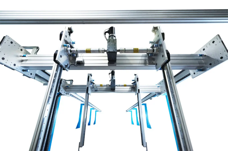
Bearings
Bearings Used in Gantry Systems
08 August, 2026
36 min read
Gantry systems move a carriage, tool, robot, or payload along one or more straight axes. They are used in automated assembly, material handling, machine loading, cutting, dispensing, inspection, packaging, and many other applications where motion must remain controlled over a defined travel.
The bearing system is what keeps that motion straight.
A gantry may use belts, ball screws, rack-and-pinion drives, or linear motors to create movement, but the drive should not be expected to guide the load by itself. Linear bearings and guideways support the moving structure, resist off-center forces, and maintain the position of the carriage as speed and direction change.
When the bearing arrangement is correct, the gantry moves smoothly, holds alignment, and returns to position consistently. When the bearings are undersized, poorly spaced, contaminated, or installed on inaccurate mounting surfaces, the system may bind, vibrate, wear unevenly, or lose repeatability long before the nominal bearing load rating is reached.
Pacific International Bearing Sales supplies linear bearings, guide carriages, and supporting rotary bearings for automation and motion-control systems. PIB works with customers who need the bearing arrangement matched to the gantry’s load, speed, travel, accuracy, environment, and drive design.
What Is a Gantry System?
A motion-control gantry is a structure that moves a carriage or crossbeam along one or more linear axes.
A basic single-axis gantry moves in one direction. More complex systems combine axes to create X-Y, X-Z, or X-Y-Z motion. The moving member may carry:
- A robotic gripper
- A cutting head
- A welding torch
- A dispenser
- A camera or inspection sensor
- A machining spindle
- A pick-and-place unit
- A lifting mechanism
- A complete secondary motion axis
This article focuses on automation and machine-motion gantries rather than large bridge cranes used for lifting bulk loads.
In a typical Cartesian gantry, two parallel rails support a bridge. A second axis moves across that bridge, and a vertical axis may raise and lower the end effector.
Every added axis changes the bearing load. The bearings on the base axis do not carry only the payload. They also support the bridge, the cross-axis components, the vertical axis, the end effector, cables, motors, gearboxes, and any process forces generated during operation.
What the Bearings Do in a Gantry
Gantry bearings have four main responsibilities.
First, they support the weight of the moving structure and payload.
Second, they resist forces created by acceleration, deceleration, processing, and off-center loading.
Third, they constrain the carriage so it moves along the intended path instead of rotating or shifting sideways.
Fourth, they establish the stiffness needed for positioning accuracy and repeatability.
A drive motor can move a flexible or poorly supported carriage, but it cannot make the carriage rigid. The bearings and structure determine whether the tool remains in position when the system accelerates, changes direction, or contacts the workpiece.
The bearing arrangement must manage:
- Vertical loads
- Horizontal side loads
- Axial forces along the direction of travel
- Pitching moments
- Yawing moments
- Rolling moments
- Shock and vibration
- Reversing forces
- Process-generated loads
The relative importance of each load depends on the gantry geometry.
Main Bearing Types Used in Gantry Systems
Several bearing types can be used in a gantry. The best option depends on load capacity, stiffness, speed, travel, accuracy, contamination, installation tolerance, and cost.
Profiled Linear Guide Bearings
Profiled linear guides, also called square-rail or profile-rail guides, are widely used in industrial gantry systems.
The system consists of a hardened profiled rail and one or more recirculating ball or roller carriages. The rolling elements travel between precision raceways in the rail and carriage, then recirculate through internal return passages.
Profiled guides provide:
- High load capacity for their size
- Good rigidity
- Controlled linear motion
- Resistance to loads from several directions
- Long travel limited mainly by rail length
- Availability with preload
- Compact installation height
- Replaceable or interchangeable carriage options in some series
The raceway geometry allows the carriage to resist vertical and lateral forces. With suitable carriage spacing, the system can also support substantial pitching, yawing, and rolling moments.
This makes profiled guides useful for gantries carrying overhung tools, vertical axes, robot heads, and process equipment.
Ball-type linear guides
Ball-type guides use recirculating balls between the rail and carriage.
They are commonly selected where the system requires:
- Smooth motion
- Moderate to high load capacity
- Good accuracy
- High speed
- Relatively low friction
- Broad product availability
The point or elliptical contact between the balls and raceways provides efficient motion and allows the carriage to accommodate combined loading.
Ball guides are often a practical choice for packaging, assembly, inspection, handling, and general-purpose automation.
Roller-type linear guides
Roller guides replace the balls with cylindrical rollers.
The rollers create line contact with the raceways, producing a larger contact area than a comparable ball system. This generally provides greater stiffness and load capacity within a similar installation envelope.
Roller guides are commonly considered where the gantry must support:
- Heavy payloads
- Large moment loads
- Machining forces
- High structural stiffness
- Small deflection under load
- Large moving bridges or vertical axes
The added rigidity can improve tool position under load, but it also makes the system less tolerant of mounting error.
A roller guide installed on twisted or uneven surfaces may bind more readily than a lower-preload ball guide. The supporting structure must be accurate enough to use the additional bearing stiffness.
Round-Shaft Linear Ball Bearings
Round-shaft linear ball bearings use recirculating balls that travel along a hardened cylindrical shaft.
They are available as individual bushings or as assembled pillow blocks and flanged units. Shafts may be supported only at their ends or continuously supported along their length.
These bearings can offer:
- Low friction
- Simple installation
- Cost-effective linear motion
- Easy replacement
- Open and closed bearing designs
- A range of housing configurations
- Some tolerance for mounting variation
Round-shaft systems are often used in lighter gantries, pick-and-place equipment, laboratory automation, packaging systems, and applications where extreme rigidity is not required.
Unsupported shafts
An unsupported shaft is held at its ends and spans the travel distance.
This arrangement is simple, but the shaft deflects under load. Deflection increases as the span becomes longer and can become the main limit before the bearing’s rolling capacity is reached.
A bearing with a high catalog load rating cannot prevent an undersized shaft from bending.
Unsupported shafts are therefore better suited to shorter travels and lighter moving loads.
Supported shafts
A supported shaft is mounted along its length on an aluminum or steel support rail.
Continuous support reduces shaft deflection and allows longer travel or greater load. Open linear bearings are generally used so the carriage can pass over the shaft support.
Supported shafts provide a useful middle ground between basic unsupported shafting and more rigid profiled rail systems.
They still do not offer the same moment stiffness as a properly arranged pair of profiled guides in every application. Carriage spacing and structural rigidity remain important.
Plain Linear Bearings
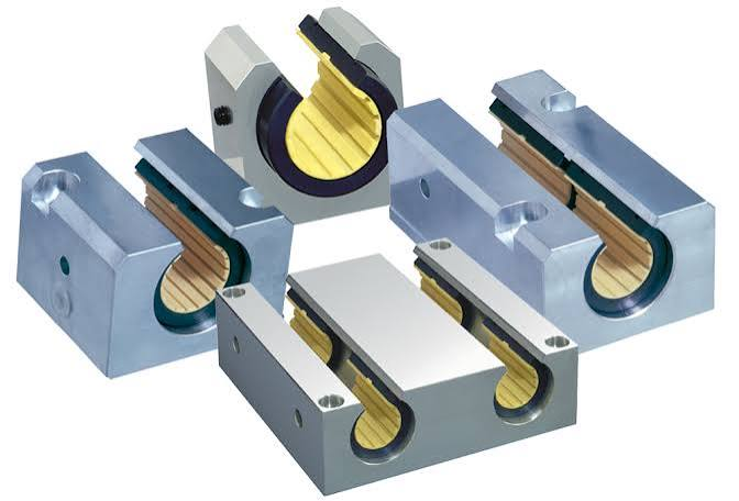
Plain linear bearings move by sliding rather than rolling.
They may use engineered polymers, composite liners, metal-backed materials, or other low-friction bearing surfaces. Some operate without external lubrication, while others can use lubricant to improve performance.
Plain bearings can be useful where a gantry must tolerate:
- Dust or debris
- Washdown
- Moisture
- Limited maintenance
- Low to moderate speed
- Shock
- Environments where grease is undesirable
They generally produce more sliding friction than rolling-element linear guides and may not provide the same stiffness or positioning accuracy.
For a packaging gantry in a dirty environment, a plain bearing may be more reliable than a highly precise rolling guide that cannot be kept clean. For a precision inspection gantry, the higher friction and clearance of a plain system may be unacceptable.
The environment and motion requirement should decide the bearing type, not precision alone.
Crossed-Roller Bearings and Slides
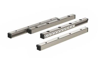
Crossed-roller systems arrange cylindrical rollers alternately at right angles between V-shaped raceways.
This geometry allows the bearing to resist loads from several directions while providing high stiffness and accurate motion.
Crossed-roller slides may be used in:
- Precision positioning stages
- Optical systems
- Inspection equipment
- Semiconductor equipment
- Short-travel gantry axes
- Fine-adjustment mechanisms
They are especially useful where motion must be smooth and deflection must remain low.
Many crossed-roller slides are intended for limited travel rather than the long strokes common in large gantries. Their use is therefore more common in a precision axis mounted on the gantry than as the main long-travel guide.
Bearings Used in the Gantry Drive System
The linear guide bearings control the path of motion, but the drive system contains additional bearings.
Ball-Screw Support Bearings
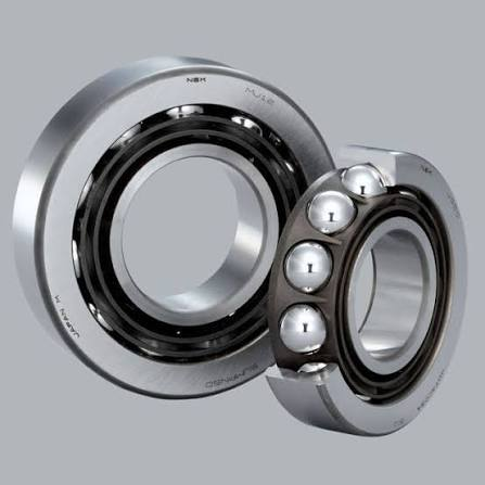
A ball screw converts motor rotation into linear movement. The screw shaft normally requires a fixed support at one end and a floating or supported arrangement at the other.
The fixed end often uses angular contact ball bearings arranged as a pair. These bearings locate the screw axially and resist the thrust generated while the nut moves the gantry.
The bearing arrangement must provide enough axial stiffness to support positioning accuracy.
If the support bearings allow excessive movement, the screw can shift before the carriage responds. The control system may command the correct position while the mechanical axis introduces lost motion.
An unsuitable support arrangement can cause:
- Axial play
- Positioning error
- Vibration
- Screw whip
- Increased bearing temperature
- Changes in preload
- Reduced screw life
With correctly selected and preloaded support bearings, the screw remains better located and reversals become more repeatable.
Belt Pulley and Idler Bearings
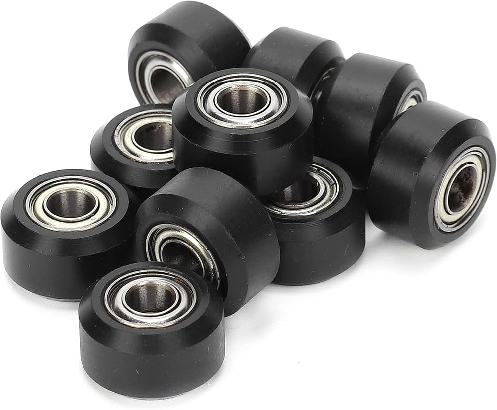
Belt-driven gantries use bearings in motor pulleys, driven pulleys, tensioners, and idlers.
These bearings carry radial load from belt tension. Depending on the pulley design and belt tracking, they may also see axial load or moment loading.
Excessive belt tension is a common problem. Increasing tension can reduce visible belt movement, but it also raises the load on pulley bearings, motor bearings, shafts, and support brackets.
Too little tension can cause:
- Tooth jumping
- Poor positioning
- Belt vibration
- Inconsistent reversal
- Tracking problems
Too much tension can cause:
- Bearing heat
- Shaft deflection
- Increased motor load
- Pulley wear
- Shortened belt and bearing life
The goal is controlled tension, not maximum tension.
Rack-and-Pinion Support Bearings
Rack-and-pinion gantries use rotary bearings to support the pinion shaft and gearbox output.
The bearing arrangement must resist forces generated at the gear mesh while keeping the pinion aligned with the rack.
If the shaft or gearbox support allows too much movement, tooth contact changes under load. This can increase backlash, noise, vibration, and wear.
Large dual-drive gantries may use one pinion system on each side of the bridge. Synchronization is essential because unequal motion can twist the crossbeam and overload the linear guides.
Cam Followers and Track Rollers
Some gantry systems use cam followers or track rollers running on hardened rails, structural sections, or custom tracks.
These bearings can provide a durable and relatively simple guidance arrangement for:
- Material-handling gantries
- Transfer systems
- Welding automation
- Long-travel equipment
- Systems exposed to debris
- Heavy but moderate-precision motion
Track roller systems may tolerate conditions that would be difficult for a compact profiled guide, but their accuracy depends heavily on track geometry, roller spacing, adjustment, and preload.
Improper adjustment can create either clearance or excessive rolling resistance.
Mounting Accuracy and Rail Alignment
Linear bearings follow the surfaces on which they are installed.
If the mounting surface is twisted, bowed, or uneven, the rail can reproduce that error. Tightening the rail bolts may then force the carriages to move along an inaccurate path.
Common installation problems include:
- Rails that are not parallel
- Mounting shoulders that are not straight
- Burrs under the rail
- Uneven bolt torque
- Paint or contamination under mounting surfaces
- Bridge plates that distort during tightening
- Carriages forced into alignment by the table
- Unsupported rail joints
These errors can create:
- High running force
- Localized wear
- Unequal carriage loading
- Position variation
- Noise
- Heat
- Shortened life
One rail is commonly established as the reference rail. The second rail is then aligned to it while the carriage assembly is moved through the full travel.
The exact procedure depends on the guide design and machine structure, but the principle remains the same: the carriages should not be forced to compensate for inaccurate mounting surfaces.
Long Gantries and Rail Joints
Long travel may require rails supplied in matched sections.
Rail joints must be positioned and aligned carefully so the carriage can pass over them without impact or load interruption.
A poor joint can cause:
- Clicking or vibration
- Raceway edge damage
- Seal damage
- Changes in running force
- Position error
- Accelerated rolling-element wear
Matched rail sections should remain in their intended order and orientation during installation.
The base structure also needs support over the full rail length. A precision rail mounted on a flexible beam will follow the beam as it deflects.
Dual-Rail and Dual-Drive Gantry Racking
A wide gantry bridge often runs on parallel guides.
If the bridge is driven from one side only, acceleration and process loads may twist the bridge. This is called racking.
Racking increases load on the carriages and can force the rails out of their intended relationship.
Dual-drive systems place a motor, screw, belt, or rack drive on both sides. These systems reduce torsional loading when correctly synchronized.
However, dual drives introduce their own risks.
If one side moves ahead of the other:
- The bridge twists.
- Carriage loads increase.
- Running resistance rises.
- Position accuracy changes across the bridge.
- The guideways may bind.
- Structural fasteners and couplings see additional stress.
Mechanical synchronization through a common shaft can work in some systems. Electronic synchronization can provide more flexibility but depends on encoder feedback, control tuning, homing strategy, and fault handling.
The bearings should not be used as the mechanism that forces two unsynchronized axes back into alignment.
Interaction With Different Drive Types
The bearing choice and drive type should be reviewed together.
Belt-driven gantries
Belts can provide high speed, long travel, and relatively low moving mass.
The guide system must control the carriage while the belt supplies the driving force. Belt compliance can affect settling time and reversal behavior, especially with heavy payloads.
Low-friction ball guides are often used, but the final choice depends on contamination and stiffness.
Ball-screw gantries
Ball screws provide accurate positioning and high thrust.
For long travel, screw critical speed, buckling, and thermal growth may become limiting factors. The linear guides must maintain alignment so the screw nut is not forced to carry side load.
Rack-and-pinion gantries
Rack-and-pinion drives are practical for long travel and high force.
Guideway stiffness helps maintain pinion engagement and gear alignment. Contamination protection is important because both the rack and linear rails may be exposed.
Linear-motor gantries
Linear motors create force without a mechanical screw, belt, or rack.
They can support high acceleration and precise control, but the guide bearings still carry the payload and maintain the motor air gap.
Because the motor can apply rapid force changes, guide stiffness, preload, and lubrication become important. Cable forces and cooling arrangements must also be included in the moving load.
What Happens When the Wrong Bearing System Is Used?
An unsuitable guide system may move the gantry during an unloaded test and still fail to meet production requirements.
A light round-shaft system may deflect under an overhung vertical axis. A heavily preloaded roller guide may bind on a fabricated frame that is not sufficiently accurate. A low-friction ball guide may fail early when exposed to abrasive dust without protection.
Before the bearing system is corrected, the gantry may show:
- Uneven motion
- High motor current
- Position variation
- Tool deflection
- Vibration
- Carriage heat
- Rapid seal wear
- Frequent lubrication needs
- Repeated bearing replacement
- Unexpected downtime
After the guide type, carriage spacing, preload, mounting accuracy, lubrication, and contamination protection are matched to the machine, the improvement is practical.
The gantry moves with more consistent resistance, maintains tool position under load, settles faster after acceleration, and requires less corrective maintenance.
The correct bearing system does not only extend component life. It improves the performance of the complete axis.
Installation Practices That Improve Reliability
Reliable gantry motion begins with the mounting surfaces.
Useful installation practices include:
- Inspect the mounting base for burrs and raised edges.
- Clean rails, carriages, and mounting surfaces before assembly.
- Identify the reference rail and reference faces.
- Follow the specified tightening sequence.
- Use controlled bolt torque.
- Align parallel rails through the full travel.
- Avoid removing carriages from rails unless the design permits it.
- Keep rolling elements from leaving the carriage.
- Protect rail joints during installation.
- Check running resistance before connecting the drive.
- Do not use the drive motor to force a binding carriage through the travel.
- Confirm that the bridge does not distort the carriage arrangement.
- Lubricate the system before full-speed operation.
- Recheck alignment after the complete payload and tooling are installed.
A gantry that moves freely before the bridge is tightened but binds afterward has an assembly or structural problem. Increasing motor torque will not correct it.
Maintaining Gantry Bearings
Maintenance should focus on changes rather than waiting for complete failure.
Useful checks include:
- Running noise
- Drive current
- Carriage temperature
- Lubricant condition
- Seal and wiper condition
- Rail cleanliness
- Fastener security
- Position repeatability
- Bridge squareness
- Backlash or lost motion
- Vibration
- Visible corrosion
Drive current is particularly useful. A gradual increase may indicate contamination, lubrication loss, alignment change, or bearing damage before the carriage becomes difficult to move manually.
Lubrication intervals should reflect actual travel and environment. A calendar-based interval may be too long for a high-cycle packaging line and unnecessarily short for an intermittently used inspection system.
Applications for Gantry Bearing Systems
Gantry bearings are used across many industries and machine types.
Common applications include:
- Cartesian robots
- Pick-and-place systems
- Palletizing equipment
- Machine loading and unloading
- CNC cutting systems
- Laser and plasma equipment
- Welding gantries
- Dispensing systems
- Packaging machinery
- Assembly automation
- Inspection systems
- Medical imaging and laboratory automation
- Electronics production
- Printing equipment
- Material-transfer systems
- Warehouse automation
The same basic bearing principles apply across these systems, but the priorities change.
A machining gantry may prioritize rigidity and deflection. A packaging gantry may prioritize speed and cycle life. A medical or inspection system may prioritize smoothness, noise, and repeatability. A material-handling system may prioritize long travel and contamination tolerance.
Frequently Asked Questions About Gantry Bearings
What bearings are commonly used in gantry systems?
Profiled linear ball or roller guides are common in industrial gantries. Round-shaft linear ball bearings, plain linear bearings, track rollers, and crossed-roller slides may also be used depending on load, travel, accuracy, and environment.
Are ball-type or roller-type linear guides better for a gantry?
Ball guides usually provide a practical balance of speed, load capacity, smoothness, and cost. Roller guides generally provide greater stiffness and load capacity but require more accurate mounting.
The correct choice depends on the gantry rather than one guide type being universally better.
How many bearing carriages should a gantry use?
Many gantries use two parallel rails with two carriages on each rail. Other arrangements can work depending on the load and structure.
The decision should be based on moment loading, carriage spacing, structural stiffness, and load distribution rather than carriage count alone.
Why does a gantry bind after assembly?
Common causes include rails that are not parallel, distorted mounting surfaces, excessive preload, uneven bolt tightening, bridge twist, contamination, or a carriage installed incorrectly.
Can linear bearings carry moment loads?
A carriage can resist some moment load, but the complete capacity depends strongly on carriage length, rail arrangement, preload, and bearing spacing.
Using multiple carriages with adequate spacing usually provides better moment resistance than relying on one compact carriage.
What is preload in a linear guide?
Preload creates controlled internal contact between the rolling elements and raceways. It reduces clearance and increases rigidity.
Too much preload increases friction and makes the guide more sensitive to misalignment.
Why do gantry bearings wear unevenly?
Uneven wear may be caused by an off-center load, bridge distortion, incorrect rail alignment, uneven mounting surfaces, contamination, or one carriage carrying more load than the others.
How are linear guides lubricated?
Many use grease applied through lubrication ports in the carriage. Oil systems may be used in certain high-speed or centralized-lubrication applications.
The correct lubricant and interval depend on the product and operating conditions.
Should gantry rails be covered?
Rails should be protected when the process generates chips, abrasive dust, fibers, welding spatter, liquid contamination, or other debris that the carriage seals cannot manage alone.
Can a linear guide compensate for an inaccurate frame?
Only to a limited extent. A rigid, preloaded guide can bind when mounted on an inaccurate frame.
The machine structure and rail mounting surfaces must meet the alignment requirements of the selected guide.
Why is one side of a dual-drive gantry overloaded?
The drives may be out of synchronization, the bridge may be twisted, the rails may not be parallel, or the payload may be off-center.
The bearings should not be expected to correct disagreement between the two drives.
What bearing is best for a dirty gantry application?
The answer depends on the contamination, load, speed, and accuracy requirement. A protected profiled guide may work, while a plain bearing or track roller system may be more practical in an environment where complete sealing is difficult.
What should be checked when gantry bearings fail repeatedly?
Review rail alignment, mounting-surface accuracy, carriage preload, load distribution, moment loads, lubrication, contamination protection, drive synchronization, and structural deflection.
Repeated bearing failure usually indicates that the bearing is responding to a system condition.
Final Considerations
The bearings in a gantry system do more than reduce friction. They establish the path of motion, support the moving structure, resist moment loads, and help the axis maintain position under acceleration and process force.
Profiled ball guides are practical for many general automation systems. Roller guides provide greater stiffness for heavier or more demanding equipment. Round-shaft bearings, plain bearings, crossed-roller slides, and track rollers each have applications where their particular balance of cost, accuracy, contamination tolerance, and load capacity makes sense.
The bearing type is only one part of the result. Rail spacing, carriage spacing, preload, mounting accuracy, lubrication, structural stiffness, drive synchronization, and contamination protection all determine how the gantry performs in service.
The PIB online catalog is a useful starting point for reviewing linear ball bearings, rails, carriages, and supporting rotary bearings for gantry drive systems. For a new or recurring gantry application, PIB can also help review the load arrangement, travel, speed, mounting conditions, and environmental requirements before a bearing configuration is selected.