Your cart is empty
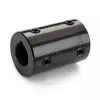
 Short Rigid Couplings
 Controlflex Couplings
 Jaw Couplings
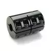
 Oldham Couplings
 Bearing Locknuts – TCN
 Double Wide Shaft Collars
 Heavy Duty Shaft Collars
 International Series Shaft Collars
 Keyed Shaft Collars
 Mountable Shaft Collars
 Quick Clamping Shaft Collars
 Set Screw Shaft Collars
 Thin Line Shaft Collars
 Threaded Shaft Collars – Pacific International Bearing Products
 Two-Piece Shaft Collars
 Friction Bearing Universal Joints
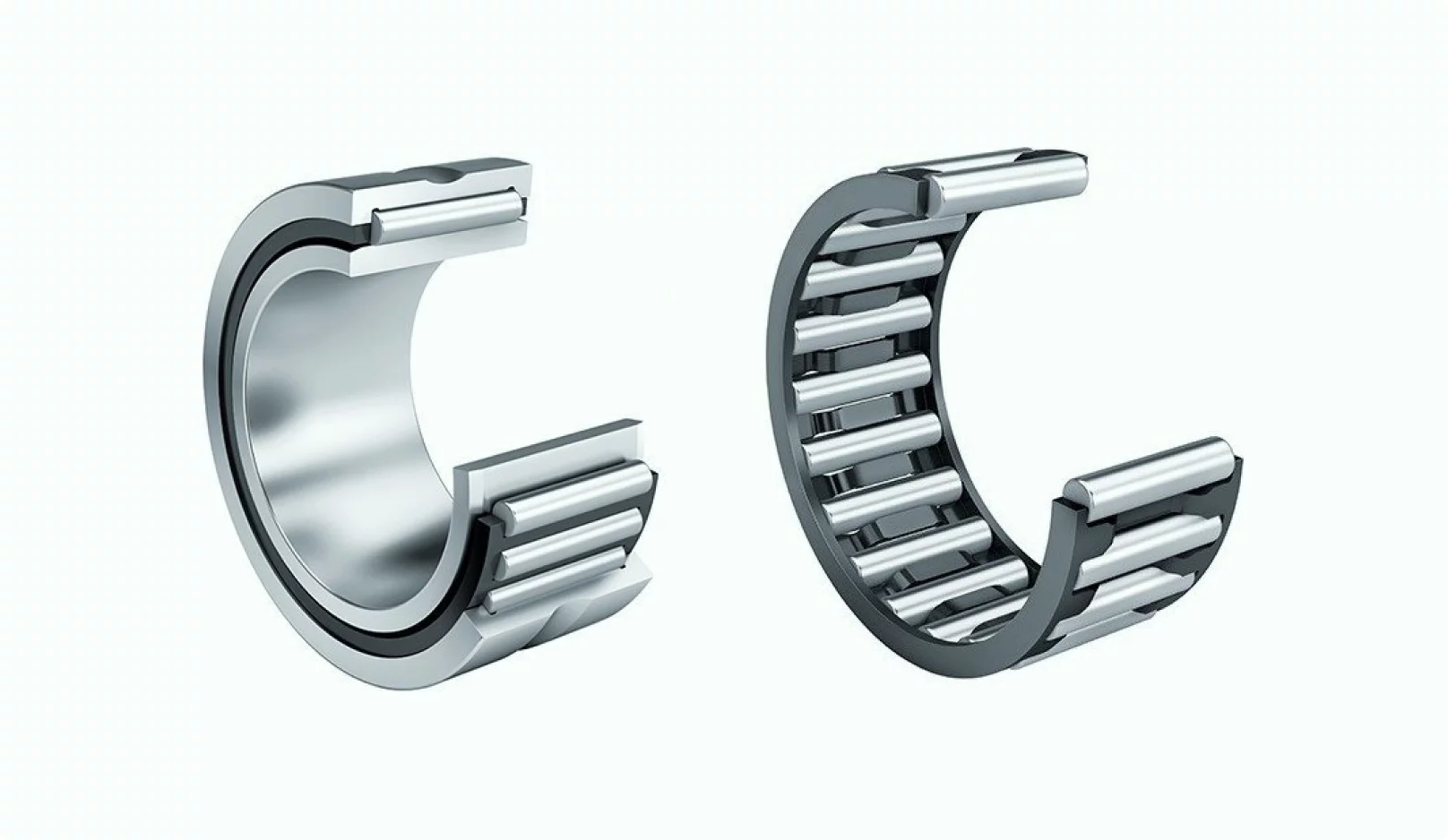
 Needle Bearing Universal Joints
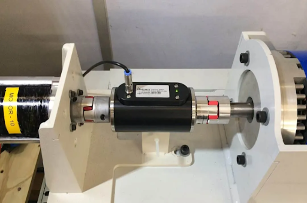
Bearings
Rotary Torque Sensors, Accurate Rotational Force Measurements
14 November, 2025
22 min read
Pacific International Bearing Sales (PIB) offers advanced rotary torque sensors engineered for highly accurate rotational force measurements – an essential capability for monitoring and controlling torque in rotating systems. Whether you’re dealing with a robotic arm’s joint, an engine’s drive shaft, or an industrial gearbox, knowing the precise torque in real time can be the difference between smooth operation and mechanical failure. In this article, we’ll explore what rotary torque sensors are, how they work, and why they’re crucial for modern rotating machinery. We’ll also look at key features, typical specifications, and how using these sensors can improve performance and reliability. Finally, we’ll answer some frequently asked questions and guide you on finding the right sensor in the PIB online catalog.
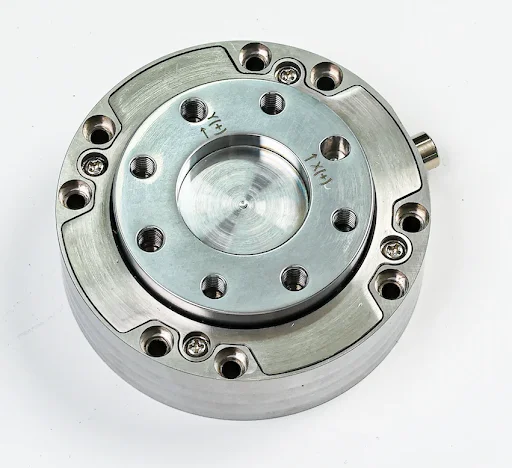
What is a Rotary Torque Sensor?
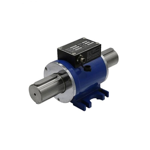
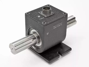
A rotary torque sensor (also known as a rotating torque transducer) is a device that measures the twisting force – or torque – on a rotating shaft. In simple terms, torque is the rotational equivalent of linear force; it’s what causes a shaft to turn. Rotary torque sensors are designed to be installed in-line with a spinning shaft or drivetrain so that as the shaft twists under load, the sensor detects and quantifies that torque in real time.
Unlike reaction (static) torque sensors which measure torque on a stationary element, rotary torque sensors allow the shaft to continuously rotate while measuring. This makes them indispensable for dynamic applications where the component under test or in operation is spinning: for example, measuring the output torque of a motor running at speed, or monitoring the twisting force on a robotic joint during movement. By capturing live torque data, rotary sensors enable engineers and control systems to monitor performance, ensure safety, and fine-tune control in applications ranging from automotive testing to robotics.
How Do Rotary Torque Sensors Work?
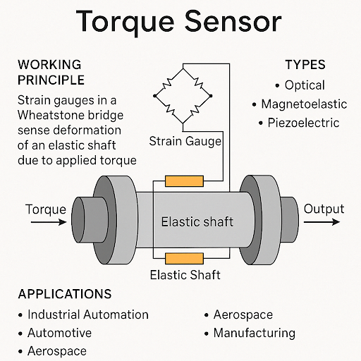
Most rotary torque sensors leverage the proven technology of strain gauges bonded to a rotating shaft element. When torque is applied to the shaft, it undergoes a slight twist (deformation). Strain gauges – tiny sensors whose electrical resistance changes with deformation – detect this twist. The change in resistance is converted into an electrical signal proportional to the torque.
Transmitting that torque signal from a spinning shaft to a stationary receiver is a key engineering challenge. There are two primary methods used in modern rotary torque sensors:
- Contact-based transmission (Slip Rings): Some rotary sensors use electrical slip rings and brushes to maintain an electrical connection between the rotating sensor shaft and the stationary output. The strain gauge signal passes through the slip rings to the readout instrumentation. This method is reliable for many applications but can introduce wear over time and may add electrical noise at high speeds. Slip-ring based sensors are often used for high-torque, low-speed scenarios, since they can handle continuous or static torque without needing the shaft to stop, but they have RPM limits due to friction and wear.
- Non-contact transmission (Wireless or Inductive): In many of rotary torque sensors, the signal is transmitted without direct contact. These non-contact rotary torque sensors use technologies like rotary transformers, inductive coupling, or wireless telemetry to send the strain gauge signal across a small gap from the rotating shaft to a stationary pickup. Because there’s no physical contact, these sensors have no wear components and can operate at higher speeds (thousands of RPM) with excellent signal fidelity. Non-contact designs are ideal for applications requiring high-speed rotation or long-term maintenance-free operation. They often incorporate on-shaft electronics to convert the strain gauge output to a digital signal or a radio frequency signal that can be picked up by a stationary coil or antenna.
In both types, the end result is an electrical output (analog or digital) that corresponds to the real-time torque on the shaft. This output can be fed into a control system, data acquisition device, or display. Modern rotary torque transducers frequently include built-in conditioning like amplification or even digital conversion on the rotor, providing high-level outputs (e.g. 0-10 V, 4-20 mA, or digital streams) directly, which simplifies integration into control systems.
Why are Rotary Torque Sensors Important?
Accurate torque measurement in rotating systems is crucial for performance, safety, and efficiency. Here are a few reasons why engineers and operators insist on rotary torque sensing in their systems:
- Performance Optimization: By monitoring torque in real time, you can ensure motors, engines, and machines operate at their peak efficiency. For instance, in an automotive engine test, a rotary torque sensor on the crankshaft helps measure output torque and power, revealing how well the engine performs and if any cylinders are misfiring. In wind turbines, measuring the torque on the main shaft allows optimization of blade pitch and generator load for maximum power output and early detection of changes in aerodynamic efficiency.
- Precision Control: Many advanced systems (like collaborative robotic arms or precision assembly machines) use torque feedback for fine control. A robot joint equipped with a torque sensor can detect subtle changes in force – enabling delicate maneuvers like a robotic gripper applying just the right amount of force, or allowing the robot to sense a collision and stop immediately for safety. In electric motor drives, torque feedback helps in achieving precise speed and torque control profiles, improving product quality (e.g., consistent torque during bolt tightening in manufacturing) and preventing over-torquing.
- Preventative Maintenance and Safety: Monitoring torque can act as an early-warning system. If a machine starts to require more torque to do the same work (indicating friction or wear increase), or if sudden torque spikes occur (perhaps due to a jam or crash in a machine), the sensor picks it up instantly. This data can trigger alarms or automatic shutdowns to prevent mechanical damage or safety incidents. For example, if a pump’s shaft begins to seize and torque rises beyond normal, a torque sensor can alert operators before a catastrophic failure occurs.
- Quality and Testing: In product development and testing (R&D), rotary torque sensors are essential for characterizing performance. Engineers use them in test stands for motors, transmissions, gearboxes, and more to gather precise torque vs speed data, which informs design improvements. Because the sensors provide quantifiable measurements, they remove guesswork and enable data-driven tuning and validation.
In summary, rotary torque sensors provide insight into the “twisting” forces inside rotating machinery, which is invaluable for improving control algorithms, ensuring safe operation within design limits, and optimizing overall system performance. They essentially give rotating machines a form of “sensory feedback” for their own torque output.
Key Features of Modern Rotary Torque Sensors
Rotary torque sensors from PIB are engineered with a focus on precision, durability, and ease of integration. Some key features and specifications to look for include:
- High Accuracy and Resolution: Quality torque transducers offer excellent accuracy (often on the order of ±0.1% to ±0.5% of full scale), so you can trust the measurements. High resolution outputs mean even minute changes in torque are detectable. This level of precision is critical for sensitive applications like fine torque control in robotic surgery equipment or calibration of engine test rigs.
- Excellent Repeatability: A good sensor will give you the same reading under the same conditions every time. Repeatability (e.g., ±0.1% FS) ensures that control systems can rely on consistent feedback. This is important for maintaining process stability in automated systems – if the torque reads 50.0 N·m now and the same 50.0 N·m later, the system can behave predictably.
- Robust Overload Protection: Industrial torque sensors typically have overload safety margins (for example, 150% of rated torque safe overload, and an ultimate overload of 200% or more). This means the sensor can withstand occasional torque spikes beyond its rated range without damage. Overload protection preserves the sensor’s integrity in the real world, where unexpected shocks or stalls can occur. It also gives peace of mind that a transient event won’t ruin the transducer (avoiding costly downtime).
- Wide Measurement Ranges: Rotary sensors come in various rated torque ranges – from tiny fractions of a Newton-meter (for micro motors and delicate mechanisms) up to tens of thousands of Newton-meters (for large industrial equipment). PIB’s portfolio covers a broad spectrum, so customers can choose a sensor that closely matches their required range for optimal accuracy. Many models even offer multiple range options or can be custom-tailored to specific capacities.
- High Speed Capability: Because many rotating systems spin at thousands of revolutions per minute, rotary torque sensors are built to handle high RPM without losing accuracy or overheating. Non-contact transmission models can typically run at 3,000–10,000 RPM or more continuously. Even slip-ring models are engineered with precision bearings and contacts to allow rotation (hundreds to a few thousand RPM, depending on design). Always choose a sensor rated above the maximum speed of your application for reliable results.
- Temperature Compensation: Changes in temperature can affect strain gauge readings. High-quality sensors include temperature compensation circuits that ensure the output remains stable across a wide operating temperature range (e.g., from -20°C up to +80°C). This means whether your equipment is cold-starting on a winter morning or running hot after hours of operation, the torque readings remain accurate.
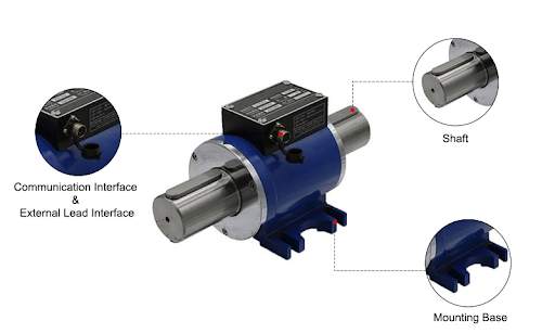
- Rugged, Compact Construction: Rotary torque transducers are often installed in industrial environments or inside machines, so they need to be robust. PIB’s sensors feature durable metal housings (stainless steel or high-strength aluminum), sealed bearings, and environmental protection ratings (often IP65/IP66 or even IP67 on some models) to keep dust, coolant, or moisture out. Despite their toughness, they are designed to be as compact and lightweight as possible for easy integration – a critical factor for robotics or retrofitting existing machinery.
- Flexible Output Options: Depending on the model, the sensor might provide a raw analog mV/V output from the strain gauge bridge (requiring an external amplifier for signal conditioning) or include integrated electronics that output amplified signals like ±10 V, 4-20 mA current loops, USB digital data, or even wireless telemetry. Having the right output interface makes it simpler to hook the sensor into your system’s controller or data logger. Some advanced models even output a pulse frequency or have built-in rotation angle/speed sensors, providing multiple data streams (torque and RPM) simultaneously.
With these features in mind, you can see that modern rotary torque sensors are not generic one-size devices, but carefully engineered components. They marry mechanical precision (in the strain sensing element and bearings) with electronic sophistication (signal transmission and conditioning) to deliver reliable torque data under real-world conditions.
Types of Rotary Torque Sensors and Examples
Rotary torque sensors can be categorized by their signal transmission method and use case. Here’s a breakdown of common types with examples from PIB’s offerings:
Slip-Ring Rotary Torque Sensors:
These sensors use physical slip rings to carry the signal from the rotating shaft. They are typically used when you need to measure high torque at lower rotational speeds or even static torque while still allowing some rotation. They excel in durability and can handle continuous operation in one direction or limited-angle oscillation. For example, PIB’s model TQ908D is a high-capacity slip-ring torque sensor rated for 200 N·m up to 2000 N·m ranges. It can tolerate up to ~100 RPM continuous rotation. Similarly, the TQ908G model uses slip rings and covers moderate to high torques (around 5 N·m up to 1000 N·m) but with a higher speed capability (up to ~1800 RPM). These slip-ring designs are well-suited for heavy-duty industrial applications like torque monitoring on rotary indexing tables, winders, or the base joint of a large robot, where the rotation speed isn’t extremely high but the torques are significant. They also feature high accuracy (TQ908G, for instance, can achieve ±0.1% FS accuracy on certain ranges) and IP67 sealing for use in harsh environments.
Non-Contact Rotary Torque Sensors:
These are designed for high-speed and maintenance-free operation, as they have no rubbing contacts. Within this category, there are purely passive ones that transmit the raw strain gauge signal via transformer coupling, and others that have built-in electronics. PIB’s TQ908A and TQ908B are examples of non-contact sensors that use transformer coupling to send the analog strain gauge signal off the rotor. They have shaft connections (like keyed shafts) on both ends to be inserted into a drive line. TQ908A covers a wide range of torque from very low (around 0.1 N·m) to mid-range (~500 N·m) and can spin up to 4000 RPM. TQ908B focuses on mid-range torques (starting ~5 N·m up to 500 N·m) also at high RPM. For very small torques, PIB offers TQ908C, a micro capacity rotary sensor (measuring as low as 0.1 N·m up to 5 N·m) which is great for tiny motors or precision instrument drives. All of these are compact and virtually wear-free, and they deliver a millivolt-level signal that can be amplified externally. They achieve roughly ±0.2% full-scale accuracy and excellent repeatability, making them reliable for tasks like motor efficiency testing or robotic joint torque feedback where you don’t want the sensor to introduce friction or drag.
- Integrated Electronics Rotary Sensors: Some applications demand an easy-to-read signal without external amplifiers, especially for long cable runs or noisy electrical environments. For these, integrated electronics on the sensor can condition the signal on the rotor or stator. PIB’s TQ908F is an example of a high-speed, non-contact rotary torque transducer that includes on-board signal conditioning. It outputs a frequency signal (typically a pulse frequency between 5–15 kHz) proportional to torque, and can also provide standard analog outputs like 0–10 V or 4–20 mA – all without any external conditioner. The TQ908F is designed for high RPM (up to 8000 RPM continuous, and even 15,000 RPM for short durations at lower torques), covering torque ranges roughly from 5 N·m up to 5000 N·m. Its combination of built-in amplification and noise-immune frequency output means it excels in applications like engine dynamometers or industrial motor test stands, where the sensor might be a few meters away from the data acquisition system and electrical noise is a concern. By producing a strong, conditioned signal, TQ908F ensures you get accurate data even in electrically noisy factory floors.
To better illustrate the differences between some of these rotary torque sensor models, the table below summarizes a few key specifications:
| Model | Dynamic Torque Range | Max Rotation Speed | Signal Output | Accuracy (Non-linearity) | Notable Features |
| TQ908A | ~0.1 N·m to 500 N·m (various ranges) | 4,000 RPM | Analog mV/V (strain gauge bridge) | ±0.2% FS (typical) | Non-contact transmission (no slip rings); keyed shaft interfaces; broad torque range for motors and actuators. |
| TQ908C | 0.1 N·m to 5 N·m (micro range) | 4,000 RPM | Analog mV/V (strain gauge bridge) | ±0.2% FS (typical) | Non-contact, ultra-low torque capability; very compact for small device testing and micro motors. |
| TQ908F | ~5 N·m to 5,000 N·m | 8,000 RPM (15,000 RPM for low ranges) | Frequency 5–15 kHz; 0-10 V or 4-20 mA (integrated amplifier) | ±0.2% FS (±0.5% on some ranges) | Non-contact & wear-free; built-in electronics for direct high-level output; excellent for high-speed, noisy environments. |
| TQ908D | 200 N·m to 2,000 N·m | 100 RPM | Analog mV/V via slip ring | ±0.2% FS (typical) | Slip-ring design for very high torque at low rotational speed or static use; rugged for heavy-duty applications. |
| TQ908G | 5 N·m to 1,000 N·m | 1,800 RPM | Analog mV/V via slip ring | ±0.1% to ±0.3% FS (range-dependent) | Slip-ring with high-quality bearings; IP67 sealed for harsh conditions; high accuracy in mid-high torque ranges. |
Choosing the Right Rotary Torque Sensor
Selecting the appropriate rotary torque sensor for your project involves balancing several factors:
- Torque Range: Choose a sensor with a capacity slightly higher than the maximum torque you expect in your application. This ensures you get accurate readings in the operating range and have a safety margin. If the range is too large, you might lose resolution; too small, and you risk overloading the sensor. PIB provides sensors spanning from very low torques (sub-1 N·m) to extremely high torques (thousands of N·m), so there’s likely an optimal model for your needs.
- Speed (RPM): Ensure the sensor can handle the rotational speed of your system. High-speed motors or spindles will require non-contact sensors that can maintain accuracy at those RPMs. For low-speed, high-torque scenarios (like a slow-turning mixing drum or a hinge that moves back and forth), a slip-ring sensor might be perfectly suitable.
- Mounting and Size: Consider how the sensor will integrate mechanically. Some sensors have flange mounts, others have shaft-to-shaft couplings or keyways. The physical length and diameter of the sensor could affect your system’s alignment or space constraints. PIB’s torque sensors come in various form factors (flange style, inline shaft, etc.) to accommodate different installation requirements.
- Output and Instrumentation: Think about what kind of signal your instrumentation or controller needs. If you already have a high-quality signal amplifier or DAQ, a mV/V output sensor could be ideal and cost-effective. If you prefer a ready-to-go signal or need long cable runs, a sensor with built-in conditioned output (voltage, current, or digital) might be better. Compatibility with your existing data acquisition system or PLC is key.
- Environmental Factors: Take into account the operating environment. If the sensor will be exposed to dust, liquids, or temperature extremes, ensure it has adequate IP sealing and temperature compensation. For instance, a food processing plant washdown environment might require at least IP66 or higher. Also consider cable routing and any potential electrical noise sources in the vicinity – a shielded cable or a frequency output can help maintain signal integrity in noisy settings.
- Dynamic vs Static Use: If you only need to measure torque during steady rotation or continuous operation, a rotary sensor is the way to go. However, if your use case involves measuring torque without any shaft rotation (or you can afford to keep the shaft static during measurement), a reaction torque sensor could be used instead. Reaction sensors are typically simpler (no rotating parts) and can be very accurate, but they obviously cannot spin. Many test setups actually use reaction torque cells attached to a static torque arm. For real-time control in rotating machinery though, a rotary sensor is usually the only option.
By evaluating these factors, you can zero in on the sensor that fits both your technical requirements and budget. Contact us and we guide you through this selection process, ensuring you get a solution that integrates smoothly and delivers the performance you expect.
Visit the PIB online catalog or mail at [email protected] to explore diverse lineups. Each product listing includes detailed specifications, and our experts are here to support you with any questions or custom requirements. Empower your rotating systems with the feedback and control that only high-quality torque sensors can provide.
Frequently Asked Questions
Q: How does a rotary torque sensor differ from a reaction (static) torque sensor?
A: A reaction torque sensor measures torque without allowing the shaft to rotate (the sensor is bolted to a fixed surface and detects twisting on a static element), whereas a rotary torque sensor is installed in a spinning shaft and measures torque during rotation. Rotary sensors use special techniques (like slip rings or wireless coupling) to send the torque signal from the moving shaft, enabling continuous real-time monitoring in rotating systems. In short, use a reaction sensor for static or slow, limited-angle measurements, and a rotary sensor for shafts that rotate continuously.
Q: What kind of accuracy can I expect from a high-quality rotary torque sensor?
A: High-quality rotary torque sensors, typically offer accuracy on the order of ±0.1% to ±0.5% of full scale, depending on the model and range. The accuracy can be slightly affected by factors like sensor range (higher capacity sensors may have slightly higher percentage error) and whether the sensor has built-in signal conditioning. Even ±0.5% FS is quite precise for most applications – for example, on a 100 N·m sensor that’s ±0.5 N·m. Many sensors also have excellent zero stability and repeatability, meaning they give very consistent readings over time. It’s always a good idea to check the spec sheet for non-linearity, hysteresis, and repeatability specs to get the full picture of accuracy.
Q: Can rotary torque sensors measure torque in both directions (clockwise and counter-clockwise)?
A: Yes. Virtually all modern torque sensors are designed to measure bidirectional torque unless specified otherwise. This means they will read positive torque for, say, clockwise twisting and negative for counter-clockwise (or vice versa, depending on how you set it up). The calibration typically covers the full range in both directions (e.g., a ±100 N·m sensor can measure 100 N·m in tightening direction and -100 N·m in the loosening direction). Bidirectional capability is important for applications like reversible drives, oscillating systems, or where you need to capture torque spikes in both directions.
Q: What are some common applications for rotary torque sensors?
A: There are many applications across industries. Some common ones include: Robotics – measuring joint torque for feedback and safety in robotic arms; Automotive testing – engine and transmission test stands use torque sensors to chart power output and efficiency; Industrial machines – monitoring torque on pumps, compressors, or mixers to detect faults or optimize performance; Aerospace – testing aircraft engine components or actuation systems for torque under load; Energy – wind turbine shafts, electric motors, generators all use torque sensors for control and analysis; and Manufacturing – for example, in a bolt tightening tool to ensure the correct torque is applied every time. Essentially, any scenario involving a rotating shaft and a need to know or control the force being transmitted is a good candidate.
Q: How do I install a rotary torque sensor?
A: Installation depends on the sensor’s configuration. Many inline rotary sensors have shafts or flanges on each end. You would typically cut the shaft you want to monitor and insert the sensor in-line, using couplings or flanges to attach the sensor’s ends to the two shaft halves. It’s important to align everything carefully to avoid introducing misalignment or bending loads on the sensor. Some sensors come with mounting bases or stators that need to be secured to prevent the sensor housing from spinning (for reaction torque support or to hold the pickup coil in place for non-contact types). Always follow the manufacturer’s installation manual. If you’re not sure, PIB’s support team can provide guidance on proper mounting hardware, alignment, and calibration once installed.
Feel free to reach out to PIB’s engineering support if you have more questions about torque sensors or need help selecting the perfect model for your application. With the right torque sensor in place, you can gain deeper insight and control over your rotating systems, leading to better performance and peace of mind.